ISSN: 0970-938X (Print) | 0976-1683 (Electronic)
Biomedical Research
An International Journal of Medical Sciences
Research Article - Biomedical Research (2016) Volume 27, Issue 4
RBC deformation analyzing within capillary blood flow using FSI method
Pedram Tehrani1*, Shahrokh Shojaei2
1Department of Mechanical Engineering, Islamic Azad University, Central Tehran Branch , Tehran, Iran
2Department of Biomedical Engineering, Islamic Azad University, Central Tehran Branch , Tehran, Iran
- *Corresponding Author:
- Pedram Tehrani
Department of Mechanical Engineering
Islamic Azad University
Iran
Accepted date: March 07, 2016
The purpose of this study is to investigate the behavior of red blood cells in order to pass through capillaries. In this research, the behavior of a single and multiple red blood cells are numerically investigated using a fluid-structure interaction (FSI) method. For calculations and comparisons of the deformation, displacements and stresses, four object points were selected and two different boundary conditions were applied to the problem. In the first, uniform velocity flow was applied at the inlet of the capillary and in the second model, the oscillating pressure was set. Through these investigations, the result reveals that the deformation in triple configuration of RBCs is more essential, sine the presence of the two additional cells above and beneath the original cell, will change the regime of flow and add extra amount to turbulency. By noticing this fact, in the uniform velocity flow pattern the results are expectable and convincing, because the displacement of triple array is greater than the single shape. But in the oscillating pressure pattern, there is no significant difference between the displacements of two corresponding points at two configurations. This output is in contrast with the results of uniform velocity flow and real situations. It shows that the assumption of uniform velocity flow at the beginning of the capillary is more logical than the oscillating pressure.
Keywords
RBC, Deformation, Capillary, Blood, Uniform velocity, Oscillating pressure, FSI method.
Introduction
Red Blood Ccells (RBCs), also named erythrocytes, are the most common type of cells in human blood which deliver oxygen (O2) to the body tissues by means of blood flow through the circulatory system. They carry oxygen in the lungs or gills and release it into tissues while squeezing through capillaries in the body. The primary function of carrying oxygen becomes possible by hemoglobin which is a chemically complex protein. When the blood circulates in the lungs, hemoglobin becomes almost completely saturated with oxygen, making the blood bright red. As red cells perfuse the capillary beds of tissues and organs, oxygen is released from the hemoglobin into the tissues. The RBC which is flowing in our body occupies 40-60% by volume ratio of blood (hematocrit), and exists in the capillaries with the large number. Human erythrocytes (red blood cells, RBCs) have a biconcave shape with an average diameter of ~8 mm [1-7]. During their 120-day life span, flowing through the human blood circulation system half a million times, RBCs experience large deformations in order to pass through capillaries as small as 3 μm in diameter [8,9]. As for the analysis of the flow phenomenon of the RBC the numerical simulation [10,11] as well as experiment observation [12] is becoming a strong tool. Particle methods, such as SPH method [13] and the MPS method [14] assumes both solid and liquid as particles, and can be used in complicated flow analysis. In case of using a particle method for the flow analysis of RBC, RBC is divided into the elastic film and internal liquid, and its deformation was investigated in detail [15]. The capability of RBCs to experience transient deformations is one of the most important factors affecting their ability to circulate [16]. Their high deformability is determinant for the passage or occlusion of capillary narrowing’s or stenosis, which are several times smaller than the RBCs [17,18]. Theoretical models have been widely used to investigate the shape transformations and the energy characteristics of free RBCs [19,20], RBCs under external forces [21,22]. They have also been used for studying the shape transformations and the energy characteristics of RBCs in a flow, principally for vessels which their radii are larger than the radii of the capillaries [23]. These models predict that the RBCs are mainly distributed in the central region of the vessel, whereas there is a zone without cells in the vicinity of the vessel walls [24]. Furthermore, in the microvasculature RBCs reach a symmetric, parachute-like shape or a nonsymmetric, slipper-like shape [24-26]. However, when the flow velocity is decreased, the parachute shape reverts to a discocyte shape [24,27]. Many researchers have investigated both simulation of fluid-structure interaction and experimental deformation of blood cells. Lim et al. has worked on the various experimental techniques for the investigation of biomechanics of single cell and molecule [28] and specifically the deformation of living cells via laser traps [29]. The study also involved an actual three-dimensional finite element model of a human red blood cell and extensive computational investigation using ANSYS were carried out on the model. The finite element model is consistent with the experimental results under direct stretching of the cell in case of using laser tweezers. Eggleton and Popel [30] investigated Large deformation of red blood cells in shear flow by simulation via the immersed boundary method while elastic membranes with varying edge constraints and Young’s moduli has been investigated by means of ANSYS by Yang et al. [31]. Jeong et al. [32] have measured the red blood cell deformation and velocity through capillaries with a diameter smaller than that of resting red blood cell in vivo by using high speed cameras to capture images of blood flow in capillaries and then estimating the deformation and velocity [33]. An in depth explanation of the theory and application of the use of Arbitrary Lagrangian- Eulerian (ALE) Methods have also been studied by J. Donea et al. [34], which explains the advantages of the ALE method in fluid dynamics and nonlinear solid mechanics [33]. Fluid-solid interaction (FSI) method is a powerful tool to study the deformation and stresses applied on the cell membrane. Therefore, in this study we developed a numerical approach by fluid-structure interaction to investigate the behaviour of a single and multiple red blood cells in a capillary.
Method
Modeling of capillary and RBCs
A two- dimensional model was adopted for biconcave shape of RBCs with details of its geometry (Figure 1) which is located between the parallel rigid plates that form vessel walls, as shown in Figure 2. The model includes of elastic particles for the RBCs membrane, fluid particles for the blood plasma and rigid particles for the vessel walls. Two model configurations were used for our investigation. In the first model, a single RBC cell is placed at the center of the capillary as appeared in Figure 2. Pure shear stress which is resulted by the fluid flow is responsible for deformation of this single RBC. In the second model, a triple array of RBCs is considered as shown in Figure 3. In this circumstance, the interaction of the RBCs is taken into account and will be determinant in flow regime and consequently affects the magnitude of shear stress. In other words, deformation of RBCs is affected by cells interaction. According to the previous studies [35,36], the approximate diameter of the capillary is in the range of 4 to 20 mm. Therefore, the average diameter of 10 mm was used in this research. For calculations and comparisons of the deformation, displacements and stresses, four object points were selected. These points as shown in Figure 4 are the critical places that are determinant in our analysis.

Figure 1: 2-Dimensional RBC model.

Figure 2: RBC between parallel plates.

Figure 3: Triple configuration of RBCs.

Figure 4: Critical points.
Boundary conditions
Two different boundary conditions were applied to the problem. In the first, uniform velocity flow was applied at the inlet of the vessel. The Reynolds number in this situation was set to 0.001 [37]. In the second model, the oscillating pressure was set at the inlet of the capillary. A sinusoidal pressure function with the amplitude of 20 mmHg and the frequency of 1 Hz was chosen according to Breyiannis’, G., and Pozrikidis’ study [38]. In both cases, fluid-structure interaction (FSI) method was used for modeling the ties between the fluid and cell membrane. Furthermore, zero pressure and the non-slip condition were applied at the outlet and the inner vessel walls, respectively.
Equations
The first principle equation that has been used is the continuity. In general, the conservation of mass is expressed by the Equation 1.
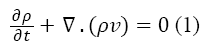
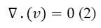
Where the ρ is the density and v is the velocity of the fluid. Because the plasma is incompressible, Equation 1 is rewritten as below:
The conservation of momentum in general is represented as Equation 3
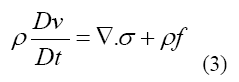
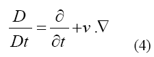
Where represents the stress tensor, f is referred to body force such as gravity and the material derivative operator D/Dt is defined by Equation 4
The kinematic condition or displacement compatibility is one of the fundamental conditions in the interface [38-40], which is given as:
 (5)
(5)
In above equation, df and ds represent the fluid and structure displacements, respectively.
Another necessary condition for the interface is dynamic condition [38] as below:
 (6)
(6)
Where  is unit normal vector and
  and
and  represents stresses of fluid and solid, respectively. These equations 1-6 are numerically solved and used for calculation of the deformations, displacements and stresses of the RBCs.
Simulation was performed using fully coupled fluid structure interaction solving capability of commercial software ADINA 8.8. For the solid and fluid model, the number of iterations and iteration tolerance is set to 1600 (each step equal to 0.001) and 0.001, respectively. All computations in this research were performed on a mesh system of 9726 cells for the fluid domain and1258 cells for the solid domain in single RBC modeling and 7610 cells for the fluid domain and 4017 cells for the solid domain in triple RBCs configuration. It is worth mentioning that the central processing unit (CPU) time of the system is about 3 times longer than that of the adopted mesh system.
Results and Discussion
The results for uniform velocity flow for single RBC and triple RBCs are shown in Figures 5-9. Figure 5 represents the stress on four selected points in single configuration of RBC. As it is shown, the point 2 has the maximum magnitude of stress and point 1 and 3 have the same corresponding stresses. Figure 6, shows the deformations of these points in single array. Deformation of single RBC and triple RBCs in uniform velocity flow are shown in Figure 7 and Figure 8. In Figure 9 the stresses at two corresponding points (point 2), in single and triple arrays are compared. As it is shown, the stress in triple configuration is higher than the single one.

Figure 5: Stresses at critical points for a single RBC.

Figure 6: Deformation at critical points for single RBC.

Figure 7: Deformation of single RBC in uniform velocity flow.

Figure 8: Deformation of triple RBCs in uniform velocity flow.

Figure 9: Comparison of stresses in single and triple arrays. 1 is related to single and 3 to triple.
Due to the shear stress in triple arrays is much more than the single one, the percentage of hemolysis is increase. The results for Oscillating pressure flow for single RBC and triple RBCs are shown in Figures 10 and 11. As it is stated, a sinusoidal pressure was applied to the entrance of the vessel. Figure 10 shows the displacement of the single RBC. Just like the uniform velocity flow, point 2 has the greatest displacement and the curve of points 1 and 3 coincide. A comparison of the displacements of analogous points in single and triple configurations is shown in Figure 11. It is obvious that in contrast with uniform velocity flow, the displacements in two cases have comparable magnitudes.

Figure 10: Displacement (m) of critical points for single RBC.

Figure 11: Comparison of displacement (m) in single and triple arrays. 1 is related to single and 3 to triple
Conclusions
In all the cases, as shown in previous figures, point 2 has the maximum amounts of displacement, deformation and stress as previous works [17,18]. Point 2 is the first location that the particles of plasma collide with the RBC cell and it acts as stagnation point. It is logical that maximum stress appear at this point. Point 1 and 3 are symmetric in a non-deformed RBC. This symmetric shape applies that these 2 points should have same displacements and inverse deformations, as it is achieved by calculations. It is reasonable that we expect more essential deformation in triple configuration of RBCs, sine the presence of the two additional cells above and beneath the original cell will change the regime of flow and add extra amount to turbulency. By noticing this fact, in the uniform velocity flow pattern the results are expectable and convincing, because the displacement of triple array is greater than the single shape. But in the oscillating pressure pattern, there is no significant difference between the displacements of two corresponding points at two configurations. This output is in contrast with the results of uniform velocity flow and real situations. It shows that the assumption of uniform velocity flow at the beginning of the capillary is more logical than the oscillating pressure.
References
- Acrivos A, Batchelor GK, Hinch EJ, Koch DL, Mauri R. Longitudinal shear-induced diffusion of spheres in a dilute suspension. J Fluid Mechanics 1992; 240: 651-657.
- Ashgriz N, Poo JY. Coalescence and separation in binary collisions of liquid drops. J Fluid Mechanics 1990; 221: 183-204.
- Bagchi P. Mesoscale simulation of blood flow in small vessels. J Biophysical 2007; 92: 1858-1877.
- Barth D. Motion of a spherical microcapsule freely suspended in linear shear flow. J Fluid Mechanics 1980; 100: 831-853.
- Adina R. ADINA Theory and Modeling Guide-Volume III: ADINA CFD & FSI. Watertown, MA, Adina R&D, Inc 2005.
- Barth D, Chim V. Constitutive equation of a dilute suspension of spherical microcapsules. Int J Multiphase Flow 1981; 7: 473-493.
- Barth D, Rallison JM. The time-dependent deformation of a capsule freely suspended in a linear shear flow. J Fluid Mechanics 1981; 113: 251-267.
- Barth D, Sgaier H. Role of membrane viscosity in the orientation and deformation of a spherical capsule suspended in shear flow. J Fluid Mechanics 1985; 160: 119-135.
- Barth D, Diaz A, Dhenin E. Effect of constitutive laws for two dimensional membranes on flow-induced capsule deformation. J Fluid Mechanics 2002; 460: 211-222.
- Wada, Kobayashi, Takahashi and Karino. A numerical simulation of the deformation of an erythrocyte, Japanese Mechanical Engineering Congress 2000; 51226: 287-288.
- Tanaka N, Takano T, Masuzawa T. 3-dimensional micro-simulation of blood flow with SPH method, Japanese Fluid Engineering Conference 2004; 712: 718.
- Gaehtgens P, Duhrssen C. Albrecht KH. Motions, deformation and interaction of blood Cells and Plasma During Flow Through Narrow Capillary Tubes, Blood cells 1980; 6: 799-812.
- Monaghan J. smoothed particle hydrodynamics. Ann Rev Astronomy Astrophysics 1992; 30: 543-574.
- Koshizuka S, Oka Y. Moving-particle semi-implicit method for fragmentation of incompressible fluid. Nuclear SciEng 1996; 123: 421-434.
- Tsubota K, Wada S, Yamaguchi T. Particle method for computer simulation of red blood cell motion in blood flow. Computer Methods Programs Biomed 2006; 83: 139-146.
- Guido S, Tomaiuolo G. Microconfined flow behavior of red blood cells in vitro. CR Physique 2009; 10: 751-763.
- Suresh S, Spatz J, Mills JP, Micoulet A, Dao M, Lim CT, Beil M, Seufferlein T. Connections between single-cell biomechanics and human disease states: gastrointestinal cancer and malaria. ActaBiomaterialia 2005; 1: 15.
- Takemura G, Takatsu Y, Fujiwara H. Luminal narrowing of coronary capillaries in human hypertrophic hearts: an ultrastructuralmorphometrical study using endomyocardial biopsy specimens. Heart 1998; 78: 85.
- Lim GHW, Wortis M, Mukhopadhyay R. Stomatocyte-discocyte-echinocyte sequence of the human red blood cell: evidence for the bilayer-couple hypothesis from membrane mechanics. ProcNatlAcadSci 2002; 99: 16766-16769.
- Khairy K, Foo J, Howard J, Shapes of Red Blood Cells: Comparison of 3D Confocal Images with the Bilayer-Couple Model. cellmolbioeng 2008; 1: 173-181.
- Evans EA, Skalak R. Mechanics and Thermodynamics of Biomembranes. CRC Crit Rev Bioeng1979; 3: 331-418.
- Kuzman D, Svetina S, Waugh RE, Zeks B. Elastic properties of the red blood cell membrane that determine echinocyte deformability. EurBiophys J 2004; 33: 1-15.
- Fedosov DA, Caswell B, Popel AS, Karniadakis GE. Blood flow and cell-free layer in microvessels. Microcirculation 2010; 17: 615-628.
- Bojan ,Gomi?s?cek. Role of red blood cell elastic properties in capillary occlusions, Physical Rev 2012; 86: 051902.
- Kaoui B, Biros G, Misbah C. Why do red blood cells have asymmetric shapes even in a symmetric flow? Phys Rev Lett 2009; 103: 188101.
- Secomb TW, Hsu R, Pries AR. Motion of red blood cells in a capillary with an endothelial surface layer: effect of flow velocity. Am J Physiol Heart Circ 2001; 281: 629-636.
- Noguchi H, Gompper G. Shape transitions of fluid vesicles and red blood cells in capillary flows .ProcNatlAcadSci 2005; 102: 40.
- Lim CT, Zhou EH, Vedula A. Experimental techniques for single cell and single molecule biomechanics. Materials SciEng 2006; 26: 1278-1288.
- Lim CT, Dao M, Suresh S, Sow CH, Chew KT. Large deformation of living cells using laser traps. ActaMaterialia 2004; 52: 1837-1845.
- Eggleton CD, Popel AS. Large deformation of red blood cell ghosts in a simple shear flow. Physics Fluids 1998; 10: 1834-1844.
- Yang R, Kubicek J. Finite Element Analysis of Elastic Membranes Under Varying Edge Constraints and Young’s Moduli. J Cell Science 1998; 109: 713-726.
- Jeong JH, Sugii Y, Minamiyama M, Okamoto K. Measurement of RBC deformation and velocity in capillaries in vivo. Microvascular Res 2006; 71: 212-217.
- Cheng LL. Bachelor thesis, Simulation of fluid flow and fluid-structure interactions in microdevices, Department of Mechanical Engineering, National University of Singapore, Session 2007.
- Donea J, Huerta A, Ponthot JP, Rodriguez A. Encyclopedia of Computational Mechanics: Arbitrary Lagrangian - Eulerian Methods, John Wiley and Sons 2004.
- Bishop J, Popel AS, Intaglietta M, Johnson PC. Effect of aggregation and shear rate on the dispersion of red blood cells flowing in venules. Am J Physiol 2002; 283:1985-1996.
- Brady JF, Morris JF. Microstructure of strongly sheared suspensions and its impact on rheology and diffusion. J Fluid Mechanics 1997; 348: 103-139.
- Brady JF, Bossis G. The rheology of concentrated suspensions of spheres in simple shear flow by numerical simulation. J Fluid Mechanics 1985; 155: 105-129.
- Alizadeh M, Tehrani P, Rahmani S. Hemodynamic simulation of blood flow in a new type of cardiac assist device named AVICENA. ProcIMech Part H 2014; 228: 824-832.
- Tehrani P, Rahmani S, Karimi A, Alizadeh M, Navidbakhsh M. Modeling of Balloon Part of a New Cardiac Assist Device Known as AVICENA. J Biomater Tissue Eng 2014; 4: 772-777.
- Batchelor GK, Green JT. The hydrodynamic interaction of two small freely-moving spheres in a linear flow field. J Fluid Mechanics 1972; 56: 375-400.