ISSN: 0970-938X (Print) | 0976-1683 (Electronic)
Biomedical Research
An International Journal of Medical Sciences
Research Article - Biomedical Research (2018) Volume 29, Issue 9
Moving sliding mode control for sEMG based prosthetic hand
DOI: 10.4066/biomedicalresearch.29-18-461
Visit for more related articles at Biomedical ResearchA prosthetic hand model designed to mimic the motion of a biological hand to take the place of an amputee's real hand. Designed prosthetic hand consist five fingers three joints on each finger. The dynamic behaviour of the prosthetic hand is estimated via SimMechanics. A sliding mode control was applied to the prosthetic hand to track the trajectory as it should be followed for any desired motion pattern without cracking. The performance of the sliding mode controller for three hand patterns of biological hand was tested.
Keywords
Sliding mode control, Tract the trajectory, Without cracking, Prosthetic hand, Electromyography.
Introduction
Researchers and prosthetics believe that control strategies should be developed for prosthetic controlled by Electromyogram (EMG) signals [1-4]. It is emphasized that a new control strategy to be developed in their work will be accepted by users at a high rate [5]. Much research has been done on grip control of prosthetic hands [6]. One of the biggest problems of the prosthesis is that the object grip force cannot be adjusted correctly. Either the force is not sufficient and the object tried to be held is damaged or the result of excessive force application is damaged. In clinical practice, prosthetics are used as an open loop without sensor feedback [1,6]. The EMG signals received by the surface electrodes from the amputee's skin are used as direct control signals. Open-loop proportional EMG control [7] is often used for simplicity and low cost reasons. Nevertheless the use of EMG signals as a direct control signal with the reason that it is small in amplitude and accompanied by environmental, hardware noises during recording does not produce successful results. For this reason, many studies have been made on the design of a multi-electrode recorder [8], the development of signal processing techniques [9] and the design of a variable time fixed adaptive filter [10].
However, some researchers who believe that open-loop EMG signaling is not sufficient for Prosthetics have developed a feedback control strategy. Pylatiuk et al. and Meek et al. have proposed and used feedback-controlled methods for controlling the gripping force of the prosthetic hand in their work [11,12]. Another method developed is automatic clutch force control. The force was gradually increased until it stopped slipping on the object being held in this control [13]. The researchers have developed a hierarchical control system with different EMG threshold levels [14,15] for the user to select four different force classes for movement (touch, hold, tighten, release). When the person touches the object, the user is used as the trigger for activating the slip sensor to perform threshold touch of the EMG signal received from the person and to prevent the object from slipping. The higher threshold EMG signal from the user indicates that the holding is taking place and the sleeping is over. In this way, the hierarchical control system allows proportional control of the grip force.
To meet the need for amputation, various prosthetic hand pieces have been designed and developed over the last fifteen years [16]. Unfortunately, no prosthesis with a good mechanical design conforms to the functional characteristics of the human hand [17]. Prostheses from commercial roads have many single-jointed (degree of freedom) fingers. Today, there are two movements that can be done widely and the dentures used are hand-held (holding) and opening (release) movements [16]. This is a design that does not allow objects to be grasped properly [18]. It has a mechanical structure with a high degree of freedom of I-Limb developed as an open source with the aim of disadvantage. However, the control structure is quite complex. Multiple control structures are used together. For this reason, it is not natural and easy to use [19]. It is still under investigation for the development of more flexible and functional artefacts [20,21]. Two problems arise in the design of an advanced prosthetic hand. One of them is to achieve mechanical design with high freedom of movement, i.e. freedom of movement, and to make motion meaningful with EMG signals, i.e. to form durable controls for orbital control [22]. Jacobsen et al. [23] used a PID controller to control an articulated mechanism, Kawanishi et al. [24] proposed a fuzzy logic controller for position control of a robot finger with four degrees of freedom (DoF) designed by Hristu et al. [25], a multi- we observed that the performance of the PID controller was not sufficient for the paramedical hand tasks where the parameter changes and the external disturbance effects were high. The parameters to control the prostheses are still needed for the parameter change robust methods because the size, and small actuators due to the design constraints on the power, but to compensate for the small motors and to produce sufficient gripping force or articulation torque, high gearing and connection mechanisms must be used. This causes significant amounts of Coulomb rubbing in the tissues [26] and prosthetic hands [27]. Slip mode control developed by Utkin is preferred as a special class of variable structure due to its robustness in robotics and other applications. Slide mode control is used to control prosthetic mechanisms against unknown and nonlinear external factors and model errors [28-31].
Overview and Highlights of Study
In this study, the human hand was modelled as fifteen joints, with three fingers on each finger. Finger was designed as flat surface in order to support well contact with object (Figure 1).

Figure 1: Overview of the study.
EMG signals were recorded from forearm and time domain features were extracted. Hand pattern recognition was realized with multi class SVM algorithm for three motions which are hand off, thumb-index finger touch, thumb-index-middle finger touch. According to classifier motion pattern, Sliding mode controller designed to control finger trajectory with high accuracy. Close loop control was supported via force sensor. Hand motion recognition and object detection algorithm are shown in Figures 2 and 3.

Figure 2: Hand motion recognition via EMG sensors.

Figure 3: Object detection algorithm with force sensor.
Pattern Recognition of Hand via EMG Signals
EMG signal recording
EMG signals were recorded from the flexor policis longus, flexor carpi radialis, brachioradialis, extensor carpi radialis, extensor digiti minimi, and extensor carpi ulnaris muscles for three-hand pattern by four-channel surface electrode group. The placement of the electrodes is shown in Figure 4 in accordance with the SENIAM protocol [32].

Figure 4: Electrode placement.
Pre-processing step of EMG signal
The EMG signal was recorded at 0.001 s intervals. The sampled signal was passed through a band pass filter (50-500 Hz). EMG signals are framed using the Englehart optimal framing method. In Englehart's study [33,34], R=256 and r=32 ms were used to determine the optimum frame size.
Feature extraction of EMG signals
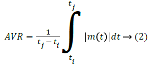
In this study, time domain features, energy of signal, maximum value, average value, RMS and variance are calculated as in Equations 1-5 and input to the classification algorithm [35].
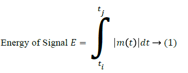
Signal Avarage Value of Signal
Efective value of signal 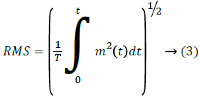
Variance of Signal: 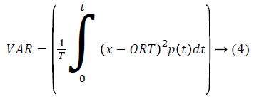
Maximum value of signal: MAX=max (m (t)) → (5)
Classification of EMG signals
Multi class SVM classifier was used to determine hand pattern. The little finger’s muscle is located at the back of the forearm, some distance away from the muscles of the other fingers. The lowest classification success was achieved for the middle and ring fingers, and this was due to the fact that their muscles are very close to each other. When the signals for these two fingers were recorded by the sEMG electrode, they overlapped each other at times. Thus, the success in sorting the signals for these two fingers was somewhat limited. However, even for these fingers, the classification success exceeded 87%.
Modeling of Anthropomorphic Hand
In order to evaluate performances of a mechanical system is used kinematical and dynamic analysis which is one of classical methods. Kinematic analysis performs the position and orientation of the mechanism resulting from the motion. Dynamic analysis describes the relationship between a particular force or moment effect and the velocity of motion, acceleration of the mechanism [36]. Analysis based on simulation are easier than mathematical solution of kinematics and dynamics [37,38]. Analysis of the kinematics and dynamics of the mechanical model is easily accomplished by block modeling without the need for mathematical modeling with the SimMechanic ToolBox. Simulation is important in terms of making pre-fabrication analyses and optimizing the design [36].
There are many studies in the literature to increase the gripping ability of multi-finger robots. Machomad et al. were focus on developing of low cost anthropomorphic prosthetic hand, and they designed 14 Dof prosthetic hand via SimMechanics first generation [39-41]. Asif was presented analytical modeling of hand via SimMechanics and PID controller response of five fingers [42]. Roshan et al. developed a robotic prosthetic hand capable of producing ten grip patterns and simulated hand pattern via SimMechanics in their study [43].
An anthropomorphic prosthetic hand (Figure 5) is designed. The prosthetic hand has 5 fingers, 15 joints and 15 DoFs, with similar appearance and size to the human hand. The thumb and forefinger have independent movements. Figure 4 exploded view of the finger. Each finger has three DoF. The prosthetic hand is actuated by 15 DC motors, which are settled in the each finger link. The thumb finger DIP, PIP and MCP joints rotate in the same axial direction. The MCP joint of the head is positioned so that it can move vertically to the joints of the PIP and DIP so that the larger object can be grasped. The axis layout scheme expressing the movements of the joints is in Figure 5.

Figure 5: Human hand and skeleton and SolidWorks image of prosthetic hand.
Numerical values of parameters used in simulation studies are given in Tables 1 and 2. These parameters were chosen were chosen taking into account the anatomy of the body of an adult individual.
| Mass (g) | Size (length × width × height) | Link shape | Number of joints | DOF | Number of actuator | Joint coupling method |
|---|---|---|---|---|---|---|
| 328.45 | 240 × 110 × 25 | Flat cylindrical | 15 | 15 | 15 | Independent motion MCP, DIP and PIP |
Table 1. General characteristic of the hand.
| MCP joint degree | PIP joint degree | DIP joint degree | PIP joint degree for thumb | DIP joint degree for thumb | Thumb circumduction degree |
|---|---|---|---|---|---|
| 0-90 | 0-90 | 0-90 | 0-90 | 0-90 | 0-150 |
Table 2. Kinematic characteristic of the hand.
Moving sliding mode controller design
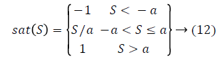
The Sliding Mode Control (SMC) method is one of the most effective and robust control methods used to control systems with nonlinear or variable parameters [44]. In other words, it provides a robust control over the control of dynamic factors that are not fully mathematically modeled and systems with disturbing effects. The system output to be steadily and durably controlled even when there are un-modeled parameters and disturbing inputs that affect the system. High-frequency oscillations, known as cracking, are a problem in the practical applications. In recent years, many methods have been proposed to reduce or eliminate these cracks [45-49]. One of the most popular methods used to reduce or eliminate the problem of cracking is the use of the term sat (s), which is continuous rather than discontinuous sgn (s). This method used to solve the cracking problem in this study.
A second-order single-input system demonstrated finger mechanism canonical form can be expressed as Equation 5 to represent the x (t) state vector, the μ (t) control signal, the f (t) [50-52].
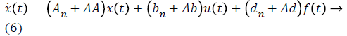
An, bn and dn represent matrices and vectors consisting of nominal system parameters, ΔA, Δb and Δd represent matrices and vectors that show the uncertainties of unknown system parameters. The sum of the uncertainties L (x, t) is written as in Equation 7.
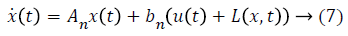
Under modeling uncertainties and external disturbing effects, the goal of the control is to ensure that the x state vector reaches and monitors the desired state vector xd. The tracking error e can be expressed as Equation 8.
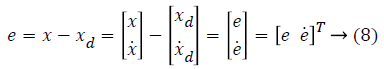
A variable slope slip surface is defined as Equation 9;
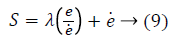
If S=λ (e/e ? )+e ?=0 then we provide S=0 for every point on the line –λ (e/e ? )=e ?. It is essential to determine the control input u which will make e=e ?=0 and provide the shift towards the origin. In addition to satisfying system performance requirements, an important aspect of designing control systems is ensuring system stability. To this end, a Lyapunov function (V (S)), defined as the square of the slip parameter as Equation 10, can be used to guarantee the stability of the sliding-type control system being attempted to be created.
V (S)=S2/2 → (10)
Lyapunov function provided the first two conditions mentioned of stability of control system (V (S)>0 and V (S)?0). If the third condition specified for the stability of the control system is S??0, it leads to an inequality. The specified inequality is determined by a positive μ parameter in Equation 11.
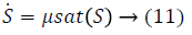
A variant is defined as the half-width of the saturation function. a value was determine as 0.1 for each joint of finger exact first joint of thumb finger. For this joint a value is 12.
In this study, genetic algorithm technique was used for optimum values of control parameters (•). The genetic algorithm was used to minimize errors [53-55].
Results
The joints of prosthetic hand SimMechanics model were transmitted the reference signals and simulated in the following order respectively: 1) hand-off, 2) thumb-index finger touch (grip object with two fingers) motions (Figure 6).

Figure 6: Prosthetic hand SimMechanics images for four hand pattern. a) Initial position: hand on; b) Pattern1: hand-off; c) Pattern 2: thumb-index fingers touch motions.
In order to better observe the transient response obtained from the dynamic model, the change that occurred in the first 0.5 s. SMC responses of joints, position errors and control signals are shown in Figures 7-10 respectively for three motions.

Figure 7: SMC response for pattern 1. a) Index-middle-ring-little fingers; b) Thumb finger.

Figure 8: Control Signal for pattern 1. a) Index-middle-ring-index fingers; b) Thumb finger.

Figure 9: SMC response for pattern 3. a) Index finger; b) Thumb finger.

Figure 10: Control signal for pattern 3. a) Index fingers; b) Thumb finger for pattern 3.
When the hand is in the open position, the reference angle values for then hand-off movements are transmitted to the prosthetic hand model, and the angular movements that are performed of the fingers are shown in Figure 7.
Index-middle-ring-little fingers with three joints except thumb reached steady state angle (90, 90, 90) degree in (0.36, 0.21, 0.21 s). Steady state time with nearly zero degree overshoots, and zero degree steady state error values. And also thumb finger reached steady state angle (30, 70, 10 degree) in (0.416, 0.28, 0.0374 s). Steady state time with nearly zero degree overshoots, and zero degree steady state error values. Control signals of joints area are shown in Figure 8.
When the hand is in the open position, the reference angle values for pattern 2: thumb-index touch motion are transmitted to the prosthetic hand model, and the angular movements that are performed by the endpoints of the five fingers are performed of the fingers are shown in Figure 9.
Index finger reached steady state angle (90, 30, 10 degree) in (0.36, 0.42, 0.436 s). Steady state time with nearly zero degree overshoots, and zero degree steady state error values. And also thumb finger reached steady state angle (-10, 30, 35 degree) in (0.386, 0.496, 0.012 s). Steady state time with nearly zero degree overshoots, and zero degree steady state error values. Control signals of joints area are shown in Figure 10.
Conclusion
The main factor in increasing the functionality of the prosthetic hand to the extent of imitating biological hand functions is the movement of the fingers. The greater the number of movements the fingers can do independently of each other, the greater the ability of the prosthetic hand to move and the more successfully it can mimic the biological hand. Within the scope of this thesis, the function of the prosthetic hand is improved by six different finger movements. Bioelectrical signals were recorded from the forearm muscles with the help of four surface electrode groups. The recorded bioelectrical signals were subjected to a series of pre-processing and feature extraction processes. An SVM classification algorithm was developed to recognition hand pattern. Dynamic modeling of five-fingered and fifteen-jointed prosthetic hand was created. Each finger of the prosthetic hand was moved by DC motor, and the position controls of the motors were provided by the designed sliding mode controller. The parameters of the sliding mode controller were determined by optimizing with GA. For the five selected hand movements, the movements of the fingers are presented in graphs and tables. Numerical results showed that sliding mode controller was obtained an efficient tracking performance.
Acknowledgements
The subject of this article, which is Beyda TA?AR's doctoral thesis, was supported by TÜB?TAK under the Domestic Doctoral Scholarship Program for Priority Areas in 2211 C. In addition, the study was supported by Firat University Scientific Research Projects Management Unit within the scope of PhD Thesis Project number MF-14.25.
References
- Childress D. Powered limb prostheses: their clinical significance. IEEE Trans Biomed Eng 1973; 20: 200-207.
- Atkins D, Heard D, Donovan W. Epidemiologic overview of individuals with upper-limb loss and their reported research priorities. J Prosthetics Orthotics 1996; 8: 2-11.
- Kyberd P, Wartenberg C, Sandsjo L, Jonsson S, Gow D, Frid J, Almstrom C, Sperling L. Survey of upper-extremity prosthesis users in Sweden and the united kingdom. J Prosthetics Orthotics 2007; 19: 55-62.
- Biddiss E, Beaton D, Chau T. Consumer design priorities for upper limb prosthetics. Disability Rehabil Assistive Technol 2007; 2: 346-357.
- Abul-Haj C, Hogan N. Functional assessment of control systems for cybernetic elbow prostheses-Part II: Application of the technique. IEEE Trans Biomed Eng 1990; 37: 1037-1047.
- Muzumdar A. Powered upper limb prostheses. Berlin Germany Springer 2004.
- Sears H, Shaperman J. Proportional myoelectric hand control: an evaluation. Amer J Phys Med Rehabil 1991; 70: 20-28.
- Clancy E, Hogan N. Multiple site electromyograph amplitude estimation. IEEE Trans Biomed Eng 1995; 42: 203-211.
- Hogan. A review of the methods for processing EMG for use as a proportional control signal. IEEE Trans Biomed Eng 1976; 11: 81-86.
- Meek S, Fetherston S. Comparison of signal-to-noise ratio of myoelectric filters for prosthesis control. J Rehabil Res Develop 1992; 29: 9-20.
- Pylatiuk C, Kargov A, Schulz S. Design and evaluation of a low-cost force feedback system for myoelectric prosthetic hands. J Prosthetics Orthotics 2006; 18: 57-61.
- Meek S, Jacobsen S, Goulding P. Extended physiologic action: design and evaluation of a proportional force feedback system. J Rehabil Res Develop 1989; 26: 53-62.
- Salisbury L, Colman A. A mechanical hand with automatic proportional control of prehension. Med Biol Eng 1967; 5: 505-511.
- Swain I, Nightingale J. An adaptive control system for a complete hand/arm prosthesis. J Biomed Eng 1980; 2: 163-167.
- Light C, Chappell P, Hudgins B, Engelhart K. Intelligent multifunction myoelectric control of hand prostheses. J Med Eng Technol 2002; 26: 139-146.
- Jones L. Dextrous hands: human, prosthetic and robotic: a survey. Pres Teleoperat Virt Env 1997; 6: 29-56.
- Bundhoo V, Park EJ. Design of an artificial muscle actuated finger towards biomimetic prosthetic hands. Proceedings of the 12th International Conference on Advanced Robotics (ICAR 05), Seattle, WA 2005; 368-375.
- Erik DE, Sanford GM. Adaptive sliding mode control for prosthetic hands to simultaneously prevent slip and minimize deformation of grasped objects. IEEE/ASME Transactions Mechatron 2013; 18.
- Weir R, Troyk P, DeMichele G, Kuiken T. Implantable myoelectric sensors (IMES) for upper-extremity prosthesis control- Preliminary work. Annu Int Conf IEEE EMBS Cancun Mexico 2003.
- Morita S, Shibata K, Zheng XZ, Ito K. Prosthetic hand control based on torque estimation from EMG signals. Proceedings of the IEEE/RSJ International Conference on Intelligent Robots and Systems (IROS 00), Tokyo, Japan 2000; 389-394.
- Morita S, Kondo T, Ito K. Estimation of forearm movement from EMG signal and application to prosthetic hand control. Proceedings of the IEEE International Conference on Robotics and Automation (ICRA 01) 2001; 3692-3697.
- Erik D. Biomimetic sliding mode control of a prosthetic hand. Proceedings of the 2010 3rd IEEE RAS EMBS Int Conf Biomed Robot Biomechatron Univ Tokyo Tokyo, Jap 2010.
- Jacobsen SC, Ko H, Iversen EK, Davis CC. Control strategies for tendon-driven manipulators. IEEE Contr Sys Magaz 1990; 10: 23-28.
- Kawanishi K, Hashizumi H, Oki Y, Nakano Y, Fukuda T, Vachkov G, Arai F, Hasegawa Y. Position and elasticity control for biomimetic robot finger. Proceedings of the 26th Annual Conference of the IEEE Industrial Electronics Society (IEKON 00), Nagoya, Japan 2000; 870-875.
- Hristu D, Babb J, Singh H, Gottschlich S. Position and force control of a multifingered hand: a comparison of fuzzy logic to traditional PID control. Proceedings of the IEEE/RSJ/GI InternationalConference on Intelligent Robots and Systems (IROS 94) 1994; 1391-1398.
- Farrell T, Weir R, Heckathorne C, Childress D. The effects of static friction and backlash on extended physiological proprioception control of a powered prosthesis. J Rehabil Res Develop 2005; 42: 327-342.
- Engeberg E, Meek S, Minor M. Hybrid force-velocity sliding mode control of a prosthetic hand. IEEE Trans Biomed Eng 2008; 55: 1572-1581.
- Utkin VI. Variable structure systems with sliding modes. IEEE Trans Autom Control 1977; 22: 212-222.
- Slotine J, Li W. Applied nonlinear control. Upper Saddle River, NJ: Prentice Hall 2002.
- Slotine J. Tracking control of non-linear systems using sliding surfaces, with application to robot manipulators. Int J Contr 1983; 38: 465-492.
- Yagiz N, Arslan YZ, Hacioglu Y. Sliding mode control of a finger for a prosthetic hand. J Vibrat Contr 2007; 13: 733-749.
- SENIAM EMG protocol. Available from: http: //www.seniam.org/ (Download date: 22 21.03.2014)
- Englehart K, Hudgins B, Parker P, Stevenson M. Time-frequency representation for classification of the transient myoelectric signal. Proceedings of the 20th Annual International Conference on Engineering in Medicine and Biology Society ICEMBS Press1998.
- Englehart K. Signal representation for classification of the transient myoelectric signal. Doctoral Thesis. University of New Brunswick, Fredericton, New Brunswick, Canada 1998.
- Hudgins B, Parker P, Scott RN. A new strategy for multifunction myoelectric control. IEEE Trans Biomed Eng 1993; 40: 82-94.
- Wan FBWT, Azmi Adly M, Amirfaiz, Irraivan Elamvazuthi W, Mumtaj B. Modeling and simulation of a multi-fingered robot hand. 2010 Int Conf Intell Adv Sys 2010; 15-17.
- Fedak V, Durovsky F, Uveges R. Analysis of robotic system motion in simmechanics and MATLAB GUI environment. MATLAB Appl Pract Eng 2014.
- The MathWorks Inc. SimMechanics Users Guide 2017.
- Rifky I, Mochammad A, Wahyu C, Ahmad N. Development of robotic hand integrated with SimMechanics 3D animation. 2016 Int Sem Intel Technol Appl 2016.
- Mochammad A, Munadi GDH, Rifky I, Jonny AP, Khusnul AM. Development of a low cost anthropomorphic robotic hand driven by modified glove sensor and integrated with 3D animation. IEEE EMBS Conf Biomed Eng Sci 2016.
- Mochammad A, Munadi GDH, Rifky I, Jonny AP, Khusnul AM. A low cost anthropomorphic prosthetic hand using DC micro metal gear motor. Proc 3rd Int Conf Info Tech Comp Electric Eng Semarang, Indonesia 2016.
- Asif MM. Analytical modeling of anthropomorphic hand using simmechanics. Proceedings of 2017 14th International Bhurban Conference on Applied Sciences and Technology (IBCAST) Islamabad, Pakistan 2017.
- Roshan KH, Mallikarjuna K, Cheruvu SK. Kinematic design of a linkage driven robotic hand for prosthetics capable of achieving ten grips. International Conference on Robotics and Automation for Humanitarian Applications (RAHA) 2016.
- Hung JY, Gao WB, Hung JC. Variable structure control: a survey. IEEE Trans Ind Electron 1993; 40: 2-22.
- Chen MS, Chen CH, Yang FY. An LTR-observer-based dynamic sliding mode control for chattering reduction. Automatica 2007; 453: 1111-1116.
- Lee H, Utkin VI. Chattering suppression methods in sliding mode control systems. Ann Rev Contr 2007; 31: 179-188.
- Ho HF, Wong YK, Rad AB. Adaptive fuzzy sliding mode control With chattering elimination for nonlinear s?so systems, simulation. Model Pract Theor 2009; 17: 1199-1210.
- Bartolini G, Punta E, Zolezzi T. Simplex sliding mode methods for the chattering reduction control of multi-?nput nonlinear uncertain systems. Automatica 2009; 45: 1923-1928.
- Yaras B, Huseynov R, Namazov M, Celikkale IE, Seker M. Fuzzy control and sliding mode fuzzy control Of DC motor. J Eng Nat Sci 2014; 32: 97-108.
- Rustamov G, Namazov M, Samet R. Sliding modes in finite-time control systems with variable structure. Proc 9th WSEAS Int Conf Autom Control Model Simul Istanbul 2007; 118-122.
- Kalayci MB, Yigit I. Pratikte Kullan?lan Baz? Kayan Kipli Kontrol Tekniklerinin Teorik Ve Deneysel ?ncelenmesi. J Eng Architect Gazi Univ Cilt 2015; 30: 131-142.
- Kose E, Abaci K, Aksoy S. Kayma Kipli Kontrolde Farkl? Eri?im Alt Yakla??mlar?n?n Analizleri. 6th International Advanced Technologies Symposium (IATS11) 2011.
- Goldberg DE. Genetic algorithms in search, optimization and machine learning. Addison-Wesley Publishing Company Inc. USA 1989.
- Man KF, Tang KS, Kwong S. Genetic algorithms: concepts and applications. IEEE Trans Indust Electron 1996; 43: 519-534.
- Haupt RL, Haupt SE. Practical genetic algorithms. Willey-Intersci Publ USA 1998.