ISSN: 0970-938X (Print) | 0976-1683 (Electronic)
Biomedical Research
An International Journal of Medical Sciences
Research Article - Biomedical Research (2018) Volume 29, Issue 10
Evaluation of significant effects on locking plates design for a 2-part fracture of the surgical neck of the humerus using finite element and statistical analysis
Ismael Mendoza-Muñoz*, Álvaro González-Ángeles, Margarita Gil-Samaniego-Ramos, Roberto LAvitia and Cicerón González-Toxqui
Universidad Autónoma de Baja California, Facultad de Ingeniería, Blvd. Benito Juárez S/N, Mexicali, Baja California, México
- *Corresponding Author:
- Ismael Mendoza-Muñoz
Universidad Autónoma de Baja California
Facultad de Ingeniería
Blvd. Benito Juárez S/N
Mexicali, Baja California, México
Accepted date: April 05, 2018
DOI: 10.4066/biomedicalresearch.29-18-313
Visit for more related articles at Biomedical ResearchSurgical options for proximal humeral fractures continue with complications in elderly patients with avascular necrosis, screw cut-out and re-operation rate. The literature suggests that these problems on the fracture fixation could be related to the implant stiffness. The main factors involved in this scenario include the physiological loading conditions, the support screws configuration, the implant material and the bone quality. The goal of this study was to determine the effects of the mentioned factors in order to establish a favourable scenario to avoid the fracture fixation failure. The finite element method in association with a two-level 24 full-factorial design model and its statistical products were used to develop this research. Results suggest that the implant material is the factor with the most relevant effect to provide stiffness on the fracture fixation, following by the support configuration. The use of a medial support with calcar screws on different qualities of bone tissue offers an optimal level of rigidity than those who do not use them. A beneficial scenario is obtained by medial support with calcar screws for the implant fixation on a 2-part surgical neck fracture of the proximal part of the humerus model.
Keywords
Biomechanics, Proximal humeral fracture, Locking plates, Medial support screws
Introduction
Proximal humerus fractures are the third most common fractures found in the world’s elderly population and these represent approximately 5-7% of all fractures. A recent American study found that surgical management of these fractures had increased by 40% in the past 20 y [1-5].
To guide treatment, Neer system classifies the fracture displacement in "parts". This scheme is not based on the number of fracture lines or segments. A "one-part" fracture is that in which the fragment is not shifted at all, moves less than 1 cm, or is not angled more than 45 degrees. There may be several fragments, but if none of them move more than 1 cm or in an angle of more than 45 degrees, the fracture of the proximal humerus is called a "one-part" fracture [6].
Approximately 50% of all proximal humeral fractures are "one-part" fractures. The treatment of a "one-part" fracture of the proximal humerus generally consists of immobilization (such as sling and swathe), ice, analgesics, and orthopaedic referral [3].
Differently, displaced fractures usually require surgery and many factors contribute to this decision-making process including the type of fracture and the degree of displacement, bone quality, patient’s activity level, and associated injuries. Surgical options include closed reduction and percutaneous fixation, open reduction and internal fixation and prosthetic arthroplasty. Locking plates provide an angular stability and a favourable bone-implant interface for comminuted fractures and osteoporosis [6-8].
Recent studies presented a high complications rate (up to 66%) after fixation of proximal humerus fractures. These results are associated to complications as avascular necrosis, intraarticular screw penetrance (screw cut-out), osteonecrosis, malunion, and implant failure. Additionally, Newton et al. showed a high incidence of loss of fixation (21.9%) in 14 elderly patients. It was noted that this prevalence was not related to the type of fracture. This might be associated with the rigidity of the implant in combination with an unsuitable medial support, in cases involving a serious underlying osteoporotic bone [1,9-11].
In order to avoid the screw cut-out and offer stability on the fracture side, it must be considered an optimal distribution between elasticity and rigidity on the implant design. Some theories reveal that for a patient with a good bone quality, a rigid implant is needed to perform with maximum stability. Instead, a semi-rigid implant is used to allow some motion and reduce the forces that are present on the bone-implant interface on patients with a low bone quality [12,13].
A positive result on conserving the reduction has been informed in clinical and practical studies that use the implant fixation with medial support screws. These studies suggest that the loss of reduction can be decreased using these screws and offer a better behavior in comparison with a locking plate fixation without the restoration of medial support. On surgical terms, the application of medial support screws is probably the most important factor that is used to avoid the mentioned complication [12,14].
A biomechanical study by Zhang et al. showed statistically a high axial and shear stiffness in the use of medial support screws in locking plates, contrary to others without medial support screws [15]. In contrast, Katthagen et al. found that the mechanical effect of additional medial support screws was not important as compared to the basic support configuration [16]. However, an interesting observation is presented by Schliemann et al. observing that although exists a discrepancy in the biomechanical studies, available clinical studies have shown the positive effects of medial support screws in locking plate fixation of proximal humeral fractures [14].
Therefore, the purpose of this study was to evaluate the statistical significance of the factors, that the literature presents as essential for the design of fixation devices for proximal humeral fractures, in order to establish their optimal levels. This was done with the support of the finite element analysis and design of experiments. The results could be a reference for researchers in this area.
Methods
Finite element method
The Finite Element Method (FEM) has a main position in the computational biomechanics. There are four principal phases implicated in the finite element analysis (FEA): model creation, model solving, and validation followed by interpretation [17-19].
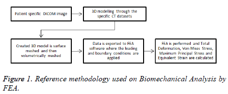
A reference methodology of the FEM starts from obtaining geometrical data of real human humerus on Digital Imaging and Communications in Medicine format (DICOM) until obtaining FEA results are presented in Figure 1.
Three-dimensional (3D) models creation: The humerus image datasets used in this experiment were from the Laboratory of Human Anatomy and Embryology, University of Brussels (ULB), Belgium. The cross-sectional images were performed with increments of 0.5 mm, and then saved in DICOM format. These images were imported to InVesalius 3.0
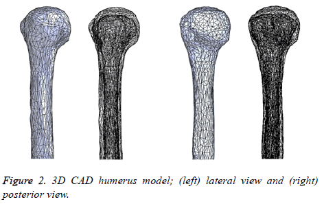
Software for generation of an STL file that describes only the surface geometry of the 3D model. Due to the geometrical complexity including the presence of additional surfaces that do not belong to the humerus (due to imperfections in the image datasets), the STL file was imported to MeshLab to improve and simplify the model with the intention of obtaining an integral model and decrease the model solving stage of the FEM. Finally, the model was imported to SolidWorks 2015 Software in order to get a final 3D CAD humerus model. Figure 2 represents the 3D CAD humerus model.
A sensitivity analysis of the bone tissues developed by Bogataj et al. reveals that trabecular bone properties own a restricted effect on the results of their biomechanical study due to the large difference in elastic modulus of cortical and trabecular bone parts (more than 20:1) [20]. Continuing with this statement, the trabecular tissue was not considered in this study.
The 3D CAD models of the locking plate system were modeled directly using SolidWorks Software. The PHILOS locking plate model was used for this study. The screws were modeled as smooth cylinders without a thread of diameter 3.5 mm according to studies by Sabalic et al. [21].
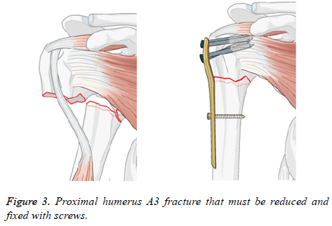
Assemblies of 3D models: A proximal fracture that is represented frequently in biomechanical studies was identified, which it is set as the removal of a portion of the surgical neck region [22-28]. This description match with a 2-part fracture of the surgical neck of the humerus entitled as proximal humeral fracture A3 in the AO classification. In Figure 3 the mentioned is shown with a short T plate to stabilize the fracture. The 3D CAD humerus model was modified in SolidWorks Software to represent this fracture with the removal from the surgical neck region.
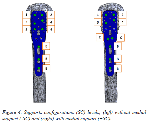
In order to study the biomechanical effect of the locking plate system for proximal humeral fractures, we proposed two support configurations (SC: without medial support (-SC) and with medial support (+SC)), both with nine screws. Figure 4 shows these (SC) including an identification code, where (C) is designated to Calcar screws, (B) to Bicortical screws and the rest of them are identified with numbers. The length of the screws for the assembly was adjusted so that the screw tip is located exactly 2 mm inside the surface of the humeral head, simulating an excellent fixation. Finally, these two screw configuration assemblies were imported to ANSYS Workbench 15.0 Software.
Meshing and materials properties: The assemblies meshed with quadratic tetrahedron elements (SOLID 187) using ANSYS Software. A sufficiently fine mesh is defined with parts using SOLID 187 elements. Also, this element type has a quadratic displacement behavior and is well suited to modeling irregular meshes [29,30]. The meshing creation was developed using the default details by ANSYS Software. This model creation generates different elements and nodes statistics for each assembly: 42471 elements and 76325 for the (-SC) assembly and 43027 elements and 77349 nodes for the (+SC) assembly.
The humerus was modeled as isotropic, linearly elastic, heterogeneous material, according to many previous studies [31-33]. An important input of Clavert et al. displayed Young’s modulus obtained by special studies of cortical and cancellous tissues of the superior end of the humerus for a healthy bone (+BT) and osteoporotic bone (-BT), both developed as isotropic materials [34]. These results are shown in Table 1 and were used for the cortical bone in our study.
| Mechanical properties | Cortical bone | Trabecular bone | ||
|---|---|---|---|---|
| Healthy | Osteoporotic | Healthy | Osteoporotic | |
| Young’s modulus | 16 GPa | 12 GPa | 550 MPa | 250 MPa |
| Poisson’s coefficient | 0.3 | 0.3 | 0.3 | 0.3 |
Table 1. Material properties for healthy and osteoporotic bone [34].
The locking plate was made from stainless steel (+PM) (E=193 GPa, v=0.31) and the screws were made from titanium alloy (E=107 GPa, v=0.36). To ensure that the type of material is a fundamental biomechanical factor for the design of this fixation device, it was proposed to use an aluminium alloy (- PM) (E=71 GPa, v=0.33) in the study, to establish a second level. This aluminium alloy is only used to make the locking plate, keeping the screws made from titanium alloy. The material properties were defined by the Engineering Data Sources of ANSYS Software. It is recommended to use an aluminium alloy because it is one of the metallic materials most used in metalworking industry and take an important place in engineering applications. Also, it has relevant properties like low weight/strength ratio, good electric and thermal conductivity, mechanical strength, etc. [35].
Boundary conditions and external loads: Some authors [21,36,37] agree that it is convenient to define a coefficient of friction of 0.3 between the bone and the plates, including a contact interactions using the surface to surface finite sliding. Following the method outlined by Zhang et al., full restraints were used between the screws and surrounding bone, and between the threaded areas of the plate and the screw head to simulate a behavior such as a tightened locking [38].
The physiological loads applied in biomechanical models for upper extremities are difficult to define due to the complex array of muscles responsible for motion, convoluted geometry and variable material properties [20]. As stated by Dahan et al., there are numerous studies that used varied procedures in order to determinate the physiological loads presented during daily life activities, and specifically for “falling on an out-stretched arm” [39]. According to the standard procedure, a vertical compression point load was applied to the humeral head [38]. The compression point load value is chosen by a summary presented in a research developed by Dahan et al. about humerus loads as found in the literature [39]. We decided to choose the magnitude of the load (L) from a study that used a method with in-vivo measurement (shoulder implant) working with different daily activities, in order to cover several scenarios of loads (550 N to 980 N). Additionally, we set a center value (770 N) beneficial to the experiment.
Finally, the bases (cross section of the distal end of the humerus) of all assemblies were fixed in all degrees of freedom.
Design of experiments (DOE)
The conclusion of an experiment is determined by a sum of factors. Factorial design (FD) allows estimation of the effect of these factors and their interactions with a minimal number of experiments [40]. In FEA, it is commonly mandatory to determine one or more response variables (equivalent (von- Mises) stress, total deformation, etc.). The material properties, model creation, and loading parameters are used as factors for a FEM and received discrete values categories or (levels) divided equitably by the range of each factor. All factors which are expected to have an effect on the response of the system can be incorporated [41].
A two-level 24 full-factorial design model with center-points was used to evaluate the effects of the quoted factors previously. Center-points are applied to verify for non-linearity of responses and to measure experimental error. Table 2 displays the factors and levels used for the proposed FD model. A combination of quantitative (load (L)) and qualitative factors (support configuration (SC), bone tissue (BT) and plate material (PM)) was used. Thus, in this FD model, there are no true center-points and are designated a pseudo-center-points. It must include a specified number of pseudo-center-points for all combinations of the levels of the qualitative factors [42]. Considering that a unique run per response evaluated is obtained in FEA, it added 1 pseudo-center-point for the numeric factor and due to the existence of three qualitative factors; there are 2 × 2 × 2=8 combinations of qualitative levels, which imply 8 pseudo-center-points. The final number of runs for the proposed FD model is 24=16 plus 8 pseudocenter- points, 24 total runs. In conclusion, we studied two varieties of (SC) (with and without medial support), two types of (BT) (osteoporotic and healthy bone), two different materials (PM) to make a locking plate (aluminium alloy and stainless steel), three (L) conditions (550, 770 y 980 N) at a 2- part fracture of the surgical neck of the humerus.
| Runs | A: Support configuration | B: Bone tissue | C: Plate material | D: Load (N) |
|---|---|---|---|---|
| 1 | - | - | - | - |
| 2 | + | - | - | - |
| 3 | - | + | - | - |
| 4 | + | + | - | - |
| 5 | - | - | + | - |
| 6 | + | - | + | - |
| 7 | - | + | + | - |
| 8 | + | + | + | - |
| 9 | - | - | - | pseudo-cp |
| 10 | + | - | - | pseudo-cp |
| 11 | - | + | - | pseudo-cp |
| 12 | + | + | - | pseudo-cp |
| 13 | - | - | + | pseudo-cp |
| 14 | + | - | + | pseudo-cp |
| 15 | - | + | + | pseudo-cp |
| 16 | + | + | + | pseudo-cp |
| 17 | - | - | - | + |
| 18 | + | - | - | + |
| 19 | - | + | - | + |
| 20 | + | + | - | + |
| 21 | - | - | + | + |
| 22 | + | - | + | + |
| 23 | - | + | + | + |
| 24 | + | + | + | + |
Table 2. Matrix for a two-level 24 full-factorial design.
In order to study the effects of the proposed factors to get a reference in the fixation device design, it is convenient to analyze them in the locking plate model as well as in the bone tissue model per the interaction that exist between both, according to the design theories initially presented. The FEM response variables selected to be studied through the proposed FD model were the maximum total deformation and the maximum equivalent stress at each 3D model. Therefore, four two-level 24 full-factorial design were developed and 96 final runs (FEA) were necessary to complete the study. Table 3 presents the values of the response variables for the 3D models (locking plate and bone tissue) of the experiment.
| Runs | Factors | On bone tissue | On locking plate | |||||
|---|---|---|---|---|---|---|---|---|
| A | B | C | D | T. Deformation (mm) | Equivalent stress (MPa) | T. Deformation (mm) | Equivalent stress (MPa) | |
| 1 | -SC | -BT | -PM | 560 | 8.1 | 71.01 | 5.6 | 874.05 |
| 2 | +SC | -BT | -PM | 560 | 5.46 | 85.37 | 4.13 | 677.8 |
| 3 | -SC | +BT | -PM | 560 | 7.97 | 75.88 | 5.51 | 873.87 |
| 4 | +SC | +BT | -PM | 560 | 5.34 | 87.08 | 4.03 | 677.6 |
| 5 | -SC | -BT | +PM | 560 | 3.79 | 69.31 | 2.64 | 900.43 |
| 6 | +SC | -BT | +PM | 560 | 2.76 | 68.15 | 2.13 | 695.14 |
| 7 | -SC | +BT | +PM | 560 | 3.68 | 74.33 | 2.56 | 899.83 |
| 8 | +SC | +BT | +PM | 560 | 2.65 | 73.02 | 2.04 | 694.9 |
| 9 | -SC | -BT | -PM | 770 | 10.69 | 94.91 | 7.39 | 1158.7 |
| 10 | +SC | -BT | -PM | 770 | 7.41 | 115.77 | 5.66 | 928.86 |
| 11 | -SC | +BT | -PM | 770 | 10.52 | 101.61 | 7.27 | 1158.5 |
| 12 | +SC | +BT | -PM | 770 | 7.25 | 123.38 | 5.52 | 928.7 |
| 13 | -SC | -BT | +PM | 770 | 5.01 | 92.73 | 3.5 | 1196.7 |
| 14 | +SC | -BT | +PM | 770 | 3.76 | 96.82 | 2.92 | 954.67 |
| 15 | -SC | +BT | +PM | 770 | 4.86 | 99.64 | 3.38 | 1196 |
| 16 | +SC | +BT | +PM | 770 | 3.61 | 104.27 | 2.79 | 954.33 |
| 17 | -SC | -BT | -PM | 980 | 13.49 | 121.65 | 9.33 | 1467.8 |
| 18 | +SC | -BT | -PM | 980 | 9.31 | 149.71 | 7.15 | 1172.7 |
| 19 | -SC | +BT | -PM | 980 | 13.28 | 130.45 | 9.17 | 1467.7 |
| 20 | +SC | +BT | -PM | 980 | 9.11 | 167.26 | 6.98 | 1172.6 |
| 21 | -SC | -BT | +PM | 980 | 6.35 | 118.87 | 4.43 | 1524.3 |
| 22 | +SC | -BT | +PM | 980 | 4.74 | 126.15 | 3.7 | 1213.2 |
| 23 | -SC | +BT | +PM | 980 | 6.16 | 127.96 | 4.29 | 1523.4 |
| 24 | +SC | +BT | +PM | 980 | 4.56 | 136.9 | 3.54 | 1212.8 |
Table 3. FEA´s results for each response variable following the proposed FD.
Minitab 17 Software was used to develop the FD models. It incorporates an analysis of variance (ANOVA), review of the residuals, identification of the standardized effects, in addition to the main effects identification and their interactions.
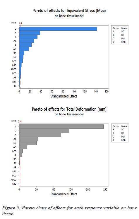
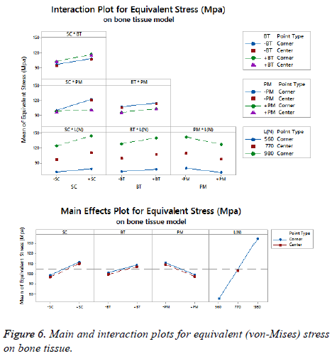
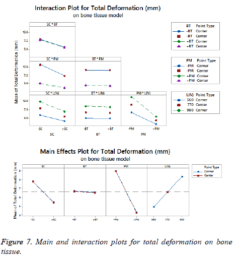
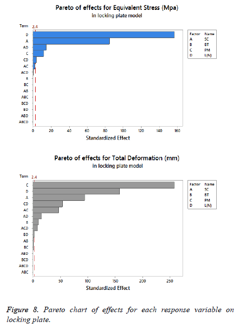
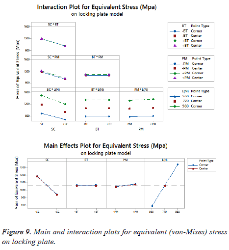
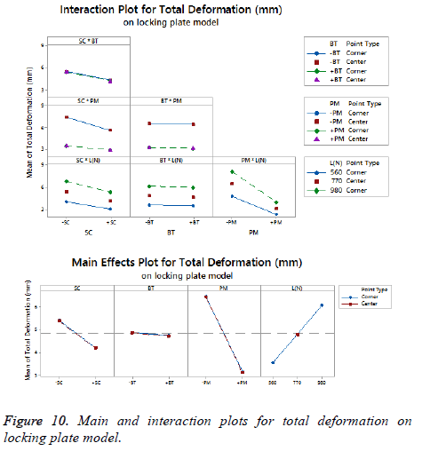
The statistical assumptions are met in the FD models according to the analysis of the residuals plots. Figures 5 to 10 show the Pareto chart of the standardized effects as well as the main effects and the interaction plots for each response variable on the 3D models.
Results
Factorial design results
We suggest dismissing the (L) as a significant parameter because it is indifferent to the fixation devices design, being fundamental to describe the operating conditions. Moreover, the results of the FDs suggest considering a lower level of (L) (560 N) to have a minimal equivalent stress and total deformation, which is logical because the mathematical models described the load as directly proportional to these response variables. The aim to utilize this factor on our study was to have a robust experiment.
A desirable structure for each response variable was developed analyzing the displayed information on Figures 5 to 10 about the effects and interactions of each factor to get minimal response variables on the 3D models (bone tissue and locking plate). The decision to propose the last scheme is to obtain a configuration that allows an optimal level of stiffness on the fracture fixation in accordance with the implant design theories.
On bone tissue model: The Pareto chart of the standardized effects presented at Figure 5 shows that (SC) is the factor that has a predominant effect on the equivalent stress followed by the (PM). In third place appears the interaction between (PM) and (SC). Finally, the (BT) is displayed as a fourth factor. Analyzing the main and interaction plot effects on Figure 6 in order to decrease the stress in the bone tissue model, the (-SC) without medial support with stainless steel (+PM) and an osteoporotic bone (-BT) would be an optimal scenario (decreasing 26% from 125.90 MPa to 93.63 MPa).
For total deformation, the evidence presented in Figure 5, places the (PM) as the main factor and the (SC) appears secondly. In third place, the interaction between (PM) and (SC) is showed. At the end, the (BT) is the factor with a low effect for this response variable. According with the interpretation on the last declaration and including the information shown in Figure 7, the stainless steel (+PM) with a medial support (+SC) and a healthy bone (+BT) must be considered to reduce the risk to appear the screw cut-out failure and afford stability (diminishing 67% from 10.76 mm to 3.6 mm).
On locking plate model: Figure 8 is shows the Pareto chart of the standardized effects displaying the (SC) as the factor that has a predominant effect on the equivalent stress followed by the (PM). In third place it presents the interaction between (PM) and (SC). According to the Pareto chart of the standardized effects, the (BT) is not a significant factor, which means that the bone tissue is not significant for this response variable. The last data in combination with the information presented in Figure 9 shows that using the medial support (+SC) with aluminium alloy (-PM) would be a favorable condition to reduce the stress in the locking plate model (reducing 23% from 1206.77 MPa to 926.37 MPa).
For total deformation, the results displayed in Figure 8 suggest the (PM) as the main factor and the (SC) appears secondly.
In third place, the interaction between (PM) and (SC) is shown. The (BT) is the factor with minimum effect for this response variable.
Agreeing to the last statement and considering the data presented in Figure 10, the stainless steel (+PM) with medial support (+SC) and a healthy bone (+BT) must be selected to get a stable fixation device (decreasing 63% from 7.44 mm to 2.79 mm).
Equivalent (von-Mises) stress distribution
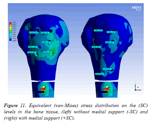
On bone tissue model: Figure 11 displays the equivalent stress distribution on the (SC) levels in the bone tissue model. The maximal stress was placed around the distal screw hole for both (SC). The stress was more uniformly distributed in the bone tissue model with medial support and a possible stress concentration was presented without a medial support. However, an important area is covering the bone tissue model with a considerable stress level along the humeral head without medial support.
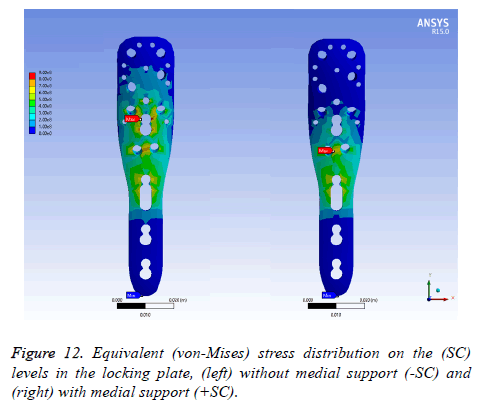
On locking plate model: Figure 12 exhibits the equivalent stress distribution of the two (SC) in the locking plate model. The maximal stress was situated over the medial screw holes for a plate with medial support, near to the osteotomy.
For a locking plate without medial support, the maximal stress was placed between the medial screw holes and a humeral head screw holes. The stress was more uniformly distributed in the locking plate without medial support in contrast to medial support.
Nonetheless, a critical area involves the locking plate with an extensive stress density without medial support.
Stiffness on fracture fixation side
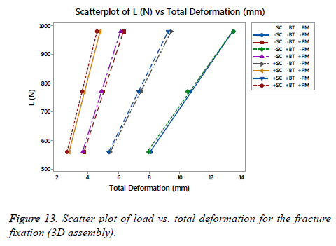
On Figure 13 is shown a scatter plot of load vs. total deformation focused on the (SC), (BT) and (PM) for the fracture fixation (3D assembly). The linear stiffness on fracture fixation is obtained from the load divided by axial displacement of the model [38]. The total deformation for the assembly, as well as the stiffness using the same number of runs proposed previously for each FD, is shown in Table 4. An important difference was presented between the fracture fixation scenarios contemplating the mentioned factors. The linear stiffness on fracture fixation was lowest in the locking plate (-SC) without medial support on an osteoporotic bone (- BT) and aluminium alloy as (-PM). Contrarily, the highest linear stiffness for the fracture fixation was presented for the locking plate using a medial support (+SC) on a healthy bone (+BT) and stainless steel (+PM). Analyzing the scatter plot, a significant effect is shown using a stainless steel (+PM) followed by the (SC), in other words, the (PM) is the factor that provides the basis to get a stiffness on the fracture fixation in combinations with the (SC). At the end, the last phrase is plausible.
| Runs | A | B | C | D | T. Deformation (mm) | Stiffness (N/mm) |
|---|---|---|---|---|---|---|
| 1 | -SC | -BT | -PM | 560 | 8.1 | 69.11 |
| 2 | +SC | -BT | -PM | 560 | 5.46 | 102.57 |
| 3 | -SC | +BT | -PM | 560 | 7.97 | 70.23 |
| 4 | +SC | +BT | -PM | 560 | 5.34 | 104.89 |
| 5 | -SC | -BT | +PM | 560 | 3.79 | 147.83 |
| 6 | +SC | -BT | +PM | 560 | 2.76 | 202.74 |
| 7 | -SC | +BT | +PM | 560 | 3.68 | 152.38 |
| 8 | +SC | +BT | +PM | 560 | 2.65 | 210.96 |
| 9 | -SC | -BT | -PM | 770 | 10.69 | 72.05 |
| 10 | +SC | -BT | -PM | 770 | 7.47 | 103.03 |
| 11 | -SC | +BT | -PM | 770 | 10.52 | 73.2 |
| 12 | +SC | +BT | -PM | 770 | 7.31 | 105.36 |
| 13 | -SC | -BT | +PM | 770 | 5.01 | 153.76 |
| 14 | +SC | -BT | +PM | 770 | 3.79 | 203.42 |
| 15 | -SC | +BT | +PM | 770 | 4.86 | 158.46 |
| 16 | +SC | +BT | +PM | 770 | 3.64 | 211.66 |
| 17 | -SC | -BT | -PM | 980 | 13.49 | 72.64 |
| 18 | +SC | -BT | -PM | 980 | 9.45 | 103.73 |
| 19 | -SC | +BT | -PM | 980 | 13.49 | 72.64 |
| 20 | +SC | +BT | -PM | 980 | 9.24 | 106.07 |
| 21 | -SC | -BT | +PM | 980 | 6.35 | 154.42 |
| 22 | +SC | -BT | +PM | 980 | 4.8 | 204.19 |
| 23 | -SC | +BT | +PM | 980 | 6.16 | 159.11 |
| 24 | +SC | +BT | +PM | 980 | 4.61 | 212.46 |
Table 4. Total deformation and stiffness for the fracture fixation.
A study developed by Zhang et al. showed a comparison of three locking plate designs made of a titanium alloy [38]. The average linear stiffness of those designs was 122.36 N/mm. Also, a study generated by Ahmad et al. offers a loaddeformation curve for different locking plates of stainless steel under a compression load to failure [43]. The mean of the linear stiffness for these plates was 203.12 N/mm. The highest linear stiffness of those locking plates had an estimated value of 275 N/mm. Despite the variation in the results of the quoted studies, they are consistent with the Hooke's Law which established that the modulus of elasticity performs as the material stiffness [44]. With higher values of Young’s modulus, the material is more rigid. For the indicated materials, the highest value of the modulus is the stainless steel followed by the titanium alloy and last, the aluminium alloy, which has the lower value of the modulus. The results for the linear stiffness presented in Table 3 are close and rational values in reference with the mentioned studies along with the cited information.
Discussion
The configuration obtained for each response variable by considering the information presented in Figures 5 to 10 for the 3D models are shown in Table 5. According to the quoted table, it was found that the most favourable scenario considering the statistical results is using the medial support (+SC), incorporated to a healthy bone (+BT) and considering the stainless steel (+PM) on a proximal humeral fracture A3.
| 3D model | Response variable | Factors | ||
|---|---|---|---|---|
| A: Support configuration | B: Bone tissue | C: Plate material | ||
| Bone tissue | Equivalent stress | -SC | -BT | +PM |
| T. Deformation | +SC | +BT | +PM | |
| Locking plate | Equivalent stress | +SC | Not significant | -PM |
| T. Deformation | +SC | +BT | +PM | |
| Statistical trend | +SC | +BT | +PM | |
Table 5. Configurations acquired after analyzing the statistical results of the FD.
These results have reinforced our view on the usage of a medial support (+SC) as the best alternative in order to decrease the equivalent stress and total deformation in the bone tissue and the locking plate models. An exception is shown for an osteoporotic bone (-BT) with stainless steel (+PM) combination, where the cited configuration from (-SC) to (+SC) was used, increases by 4% the equivalent stress (from 93.63 MPa to 97.04 MPa) on the bone tissue model and it may be contemplated as a trivial value. In addition, this result agrees with the information presented in Table 3, where is shown the use of medial support (+SC) as relevant to get the highest stiffness.
As predicted, a healthy bone (+BT) is the optimal scenario to obtain minimal values in the proposal response variables. An omission appears in the bone tissue model, being the same subject as the one presented before on the utilization of the medial support (+SC). Considering a healthy bone (+BT) and replacing the support configuration from (-SC) to (+SC), an increase of 4% (from 100.64 MPa to 104.73 MPa) must be recognized. Additionally, it is important to remark that the (BT) was not as significant to have a considerable stiffness on the fracture site as shown in Table 4. Although, it is imperative to mention that the obtained result is consistent with the statement cited before about the relationship between the modulus and the stiffness of the material; on this point, the healthy bone (+BT) is more rigid than the osteoporotic bone (- BT), being this information coherent with the literature.
The results are consistent with using stainless steel (+PM) for manufacture locking plates and to decrease the equivalent stress and total deformation on the 3D CAD models. A special case is given on the locking plate model, where replacing the aluminum alloy (-PM) by stainless steel (+PM) showed an increment of 3% on the equivalent stress (from 926.37 MPa to 954.17 MPa), being a minimal difference. In addition to the mentioned benefits, the (PM) is an important factor in order to define the stiffness on the fracture fixation as presented in Figure 13 and Table 4.
As said before, the resulting structure is recommended to patients with a good bone quality (+BT), and regarding the incidence of suffering proximal humeral fractures is frequently in patients that are older than 60 y [2-4,45], it is critical to examine the results attending this position. For studies focused on the osteoporotic bone (-BT), it is important to remember the concept of semi-rigid implant to be used on this bone tissue quality. The design theories say that this group of implants offers some motion and reduce the strain on the bone-implant interface per the forces that acting on it [12,13]. In this regard, we focused on beneficial structures to minimize the total deformation including the equivalent stress on the bone tissue model, looking to have an optimal relationship between elasticity (to prevent screw cut-out) and rigidity (to provide stability).
Returning to Table 5, the useful situation of decreasing the equivalent stress on the bone tissue model considers performing without medial support (-SC) on the osteoporotic bone (-BT) with stainless steel (+PM) for the locking plate. Making a comparison with the results presented in Figure 13 and Table 4, this configuration offers a medium stiffness (stability) that could allow some motion. Additionally, the cited structure reduces the equivalent stress by 11% (from 104.73 Mpa to 93.63 Mpa) compared with the statistically superior configuration obtained by Table 5. Next, an increment appears for the rest of the response variables leading this scenario. First, an addition of 28% (from 3.6 mm to 5.04 mm) is present on the total deformation of the bone tissue model. Second, the equivalent stress increases by 21% (954.01 MPa to 1207.14 MPa) and the total deformation by 21% (from 2.79 mm to 3.52 mm) on the locking plate model.
On the other hand, a proposed structure is obtained with the aim to minimize the total deformation on the bone tissue model considering an osteoporotic bone. Evaluating the information showed in Figure 7, the effective scenario looks to operate with medial support (+SC) on the osteoporotic bone (-BT) with stainless steel (+PM) for the locking plate. Evaluating the results shown in Figure 13 and Table 4, this structure provides a maximum stiffness only surpassed by the statistically superior arrangement obtained by Table 5. The evaluation of the effects of each response variable shows a reduction of the equivalent stress by 7% (from 104.73 MPa to 97.04 MPa) and presents an increment by 4% on the total deformation (from 3.6 mm to 3.75 mm) respectively. For the locking plate model, the equivalent stress does not show a significant difference (954.01 MPa to 954.33 MPa), while an increment of 4% appears on the total deformation (2.79 mm to 2.91 mm).
Comparisons of these configurations (ideal for osteoporotic bone), as well as the statistically obtained configuration, are shown in Table 6. The most favorable configuration looking to have a useful relationship between elasticity and rigidity is the one corresponding to reducing the total deformation on the bone tissue model. Also, the resolution is obtained by considering the primary and secondary repair mechanism after. These appear to occur only when it is established an alignment stability in conjunction with a limited inter-fragmentary motion of the fracture fragments [46-48]. This configuration offers a lower movement in comparison with its counterpart which is too elastic (additional 28% and 21% on total deformation for each model, individually).
| 3D model | Response variable | Optimal per equivalent stress | Optimal statistically (control) | Optimal per total deformation | |||
|---|---|---|---|---|---|---|---|
| Value | Increase | Value | Increase | Value | Increase | ||
| Bone tissue | Equivalent stress | 93.63 | -11% | 104.73 | - | 97.04 | -7% |
| T. Deformation | 5.04 | 0.28 | 3.6 | - | 3.75 | 0.04 | |
| Locking plate | Equivalent stress | 1207.14 | 0.21 | 954.01 | - | 954.33 | - |
| T. Deformation | 3.52 | 0.21 | 2.79 | - | 2.91 | 0.04 | |
Table 6. Contrasts between the configurations obtained by a focus on each response variable for osteoporotic bone.
According to the developed biomechanical study, it is mandatory to recognize that the obtained results on the locking plate model are not as important as the outcomes acquired on the bone tissue model per the appreciable difference between their mechanical properties (strength, modulus, etc.).
Even though the use of an isotropic model concludes in an overmuch conservative estimation of the load needed to initiate and propagate a crack [31], it is useful to understand and analyze the effects and define tendencies of studied biomechanical factors. Additionally, with a complete removal of the cancellous bone, it would simplify the FE model and reduce the computing time significantly [20].
Conclusion
The goal of this work was to analyze the significant effects of main biomechanical factors applied to the design of locking plates in proximal humeral fractures using FEM and an FD, looking for establishing an optimal configuration. The results suggest the use of medial support with manufactured locking plates of stainless steel, in order to attend the biomechanical considerations about the fracture fixation on an indistinct bone tissue (healthy or osteoporotic). These findings applied on a 2- part fracture of the surgical neck of the humerus. In spite of the extensive information obtained by experimentation, the analysis of cases in biomechanics are highly interdisciplinary and require skills in areas of biomedical engineering and biology. Additionally, the developed experimental and numerical analysis methodologies on this study remain very useful to define a trend on biomechanical models in order to make better decisions. Finally, we suggest developing new studies focusing on three- and four-part proximal humeral fractures in order to determine if the biomechanical studied factors show a similar behavior and estimate if the proposed configuration on this study is optimal on these fractures.
Acknowledgement
Authors acknowledge the Universidad Autónoma de Baja California for facilitating access and use of its facilities and equipment to carry out this research.
Conflict of Interest
We hereby state that none of the authors has any financial or personal relationships with other people or organizations that could inappropriately influence (bias) our work.
References
- Newton AW, Selvaratnam V, Pydah SK, Nixon MF. Simple radiographic assessment of bone quality is associated with loss of surgical fixation in patients with proximal humeral fractures. Injury 2016; 47: 904-908.
- Roux A. Epidemiology of proximal humerus fractures managed in a trauma center. Orthop Traumatol Surg Res 2012; 98: 715-719.
- McMahon PJ, Kaplan LD, Popkin CA. Sports medicine: in current diagnosis & treatment in orthopedics. McGraw-Hill 2014.
- Schulte LM, Matteini LE, Neviaser RJ. Proximal periarticular locking plates in proximal humeral fractures: Functional outcomes. J Shoulder Elb Surg 2011; 20: 1234-1240.
- Wanzl M, Foehr P, Schreiber U, Burgkart RH, Lenich A. Biomechanical testing to evaluate the cut-through resistance of intramedullary nails for the proximal humerus. Injury 2016; 47: 20-24.
- Thomas BJ. Orthopedic surgery, in Schwartz’s principles of surgery. McGraw-Hill, New York 2014.
- Vanderhave K. Shoulder and humerus injuries. In current diagnosis & treatment: surgery. McGraw-Hill, New York 2015.
- Smith W, Stahel P, Suzuki T, Gabrielle P. Musculoskeletal trauma surgery in current diagnosis & treatment in orthopaedics. McGraw-Hill, New York 2014.
- Shukla DR, McAnany S, Pean C, Overley S, Lovy A, Parsons BO. The results of tension band rotator cuff suture fixation of locked plating of displaced proximal humerus fractures. Injury 2017; 48: 474-480.
- Krappinger D, Bizzotto N, Riedmann S, Kammerlander C, Hengg C, Kralinger FS. Predicting failure after surgical fixation of proximal humerus fractures. Injury 2011; 42: 1283-1288.
- Schliemann B. Screw augmentation reduces motion at the bone-implant interface: A biomechanical study of locking plate fixation of proximal humeral fractures. J Shoulder Elb Surg 2015; 24: 1968-1973.
- Thanasas C, Kontakis G, Angoules A, Limb D, Giannoudis P. Treatment of proximal humerus fractures with locking plates: A systematic review. J Shoulder Elb Surg 2009; 18: 837-844.
- Kralinger F, Gschwentner M, Wambacher M, Smekal V, Haid C. Proximal humeral fractures: What is semi-rigid? Biomechanical properties of semi-rigid implants, a biomechanical cadaver based evaluation. Arch Orthop Trauma Surg 2008; 128: 205-210.
- Schliemann B. How to enhance the stability of locking plate fixation of proximal humerus fractures? An overview of current biomechanical and clinical data. Injury 2015; 46: 1207-1214.
- Zhang W. The mechanical benefit of medial support screws in locking plating of proximal humerus fractures. PLoS One 2014; 9: 3-10.
- Katthagen JC, Schwarze M, Meyer-Kobbe J, Voigt C, Hurschler C, Lill H. Biomechanical effects of calcar screws and bone block augmentation on medial support in locked plating of proximal humeral fractures. Clin Biomech 2014; 29: 735-741.
- Sawacha Z, Schrefler B. finite element modelling in musculoskeletal biomechanics in modelling methodology for physiology and medicine. Newnes 2014; 527-544.
- Gíslason MK, Stansfield B, Nash DH. Finite element model creation and stability considerations of complex biological articulation: The human wrist joint. Med Eng Phys J 2010; 32: 523-531.
- Carlson KJ, Marchi D. Reconstructing mobility. Springer, US 2014.
- Bogataj M, Kosel F, Norris R, Krkovic M, Brojan M. Biomechanical study of different plate configurations for distal humerus osteosynthesis. Med Biol Eng Comput 2015; 53: 381-392.
- Sabalic S, Kodvanj J, Pavic A. Comparative study of three models of extra-articular distal humerus fracture osteosynthesis using the finite element method on an osteoporotic computational model. Injury 2013; 3: 56-61.
- Maldonado ZM. Straining of the intact and fractured proximal humerus under physiological-like loading. J Biomech 2003; 36
