ISSN: 0970-938X (Print) | 0976-1683 (Electronic)
Biomedical Research
An International Journal of Medical Sciences
Review Article - Biomedical Research (2015) Applications of Rapid Prototyping Techniques in Bio-Materials ARTBM2015
Design Analysis of Circular External Tiba Fixator to Reduce the Stress on Bone.
1PhD Scholar, Department of Mechanical Engineering, Sathyabama University, Chennai, Tamilnadu, India
2Professor, Department of Mechanical Engineering, S.A.Engineering College, Chennai, Tamilnadu, India
- Corresponding Author:
- Praveen. R
Department of Mechanical Engineering Sathyabama University, Rajiv Gandhi Salai, OMR Chennai 600 119, India
Accepted date: July 07 2015
The paper is intended to analyze the design of circular external fixation system for bone union. It is a fixator system where threaded pins are anchored in the bone. These pins pass through the cortex on either side of the medullary space, and only a few ‘mm’ of the pin tip should protrudes through the distal cortex. The usual complications of this fixation system are loosening of the pins. These pins deform and inturn distorts the bone. To avoid the stress on the bone, the fixation technique is analyzed and the mechanical behaviour of the circular fixation device is studied. The angle between the pins in a circular fixator is usually 90º. The stresses related in the present fixation and the stress after redesign are to be studied. The fixator is designed using Pro-E and analyzed using ANSYS.
Keywords
ANSYS, Bone deformation, Circular fixator, Implant, analysis, Stress
Introduction
Ring fixators, also known as circular external fixators, utilize Ilizarov’s theory of controlled distraction histogenesis, whereby bone is fractured in the metaphyseal region and slowly lengthened [1].
This distraction process allows for bone reconstruction within the segmental defects of malunions [2], through the insertion of small Kirschner wires (K-wires) under tension and circumferential ring supports. As new bone growth occurs in the metaphyseal region, it pushes a segment of healthy bone into the defect [3].
The tension that is created by gradual distraction stimulates the formation of new bone, blood vessels, and muscle. Thus, over time, bone lengthening can occur at a rate of approximately one centimeter per month.
Design of fixator in PRO-E
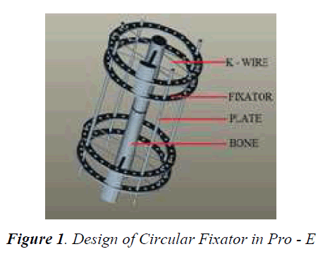
The design analysis of the Fixator structure is essential in computing the amount of stress that is being exerted on the bone. The Components of the Fixator like Plate, Fixator, K-wire are designed using Pro-E. The components are then assembled and then it is analysed using ANSYS.
Meshing of Fixator
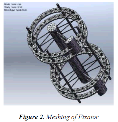
The Fixator, Designed using Pro- E is analyzed using ANSYS software. The following steps were followed,
• The Fixator designed using Pro-E is Descritized first
• The material properties like Young’s modulus, Poisson ratio, Density of material are defined.
• The nodes are placed in critical points and Varying cross sections.
• The element edge length is defined,
• Mesh size is defined and the elements are meshed by using 8 node Quadrilateral mesh. The results could be made more accurate by very fine mesh and by reduction in the mesh size.
Application of Load
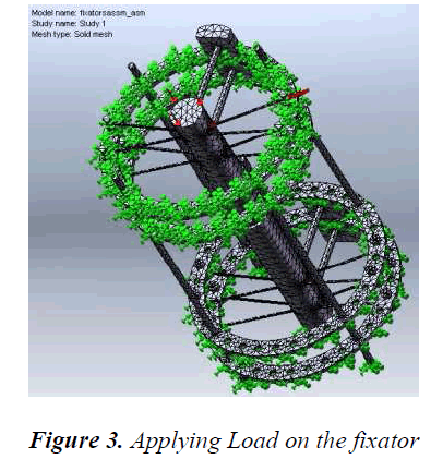
Once the meshing is done, the load has to applied on the fixaor. The following steps were followed.
• The degrees of freedom is arrested in XY direction,
• The rotation is arrested about the axis.
• All DOF is arrested in the bone and the load is applied on the structure.
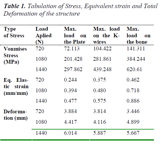
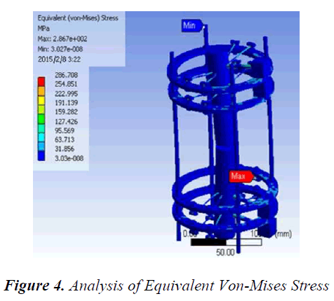
A Uniformly Distributed Load (UDL) is applied on the structure. The load is applied on the fixator structure and the analysis of stress, strain and deformation is analyzed The Von-Mises stress is analysed for the fixator designed with the angle between the adjacent K-wires for 90°. The fixator is analysed for different loading conditions for 720 N, 1080 N and 1440 N.
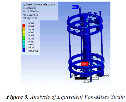
Determination of Equivalent Elastic Strain
When an elastic material is deformed due to application of external force, internal resistance is developed in the material of the body. Due to the external force there is a change in original length of the body or the body gets deformed under the external load and an internal resistance is developed. This is known as Elastic strain energy. The resultant of the elastic strain energy is known as Elastic strain energy.
The Equivalent Elastic Strain is analysed for the fixator designed with the angle between the adjacent K-wires for 90°. The fixator is analysed for different loading conditions for 720 N, 1080 N and 1440 N.
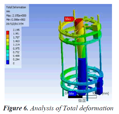
Determination of Total Deformation
The Total deformation is analysed for the fixator designed with the angle between the adjacent K-wires for 90°. The fixator is analysed for different loading conditions for 720 N, 1080 N and 1440 N.
Stress & Deformation Analysis of Fixator
Once the fixator is designed for 90º, The Vonmises stress, Equivalent Elastic Stress, Deformation are analysed from the nodal analysis by using ANSYS. The results are tabulated in the table below for different values of loads. The maximum load acting on the fixator, k-wire and bone are tabulated in the table below
Conclusion
The circular fixator was analyzed for bone union, the fixator with k-wires acts like a cantilever or simply supported beam. This is used when the load carried by the patient is very high and the load is acting at particular area of the bone.
References
- Mazhar Tayel et al “A Novel Sensor and a Proposed Setup for Remote_Measurement of Mandibular Implant Stress” National Radio Science Conference 2012; 683-689
- Jon T. Mader, et al “Staging and Staging Application in Osteomyelitis” Department of Orthopaedic Surgery, Clinical Infectious Diseases 1997; 25: 1303–1309
- Coverage position criteria _ ilizarov. Retrieved March 10, 2015, from https://my.cigna.com
