ISSN: 0970-938X (Print) | 0976-1683 (Electronic)
Biomedical Research
An International Journal of Medical Sciences
- Biomedical Research (2015) Volume 26, Issue 3
A wireless based power transmission to supply deep brain stimulators.
Department of Electrical Engineering, University of Isfahan (UI), Isfahan, Iran
- *Corresponding Author:
- Mehdi Niroomand
Department of Electrical Engineering, University of Isfahan (UI), Isfahan, Iran
Accepted date: April 24 2015
In this paper, a new wireless power transmission method is proposed to supply deep brain stimulators. By using a wireless charger, the surgery for replacing the stimulator’s batteries and all of its problems including infection, pain, and making patients uneasy, have been omitted. The Resonance inductive coupling (RIC) method is chosen among the different wireless power transmission methods and a resonance-based structure is designed. There are some simulations and practical experiments at the end of the paper which show this structure can generate 324 milliwatt power. Also, the efficiency of this system in 10mm distance is 41.62%
Keywords
Wireless power transmission; resonance inductive coupling (ric); implantable medical devices (imd); deep brain stimulators
Introduction
Nowadays, using implantable medical devices has grown significantly due to their ability to locally stimulate internal organs and/or monitor and communicate the internal vital signs to the outer world. These small devices such as deep brain stimulators (DBS), pacemakers, cardiac defibrillators and drug pumps are placed in the body to do special treatments. As with commercial portable products, IMDs share the same needs to reduce the size, weight and power [1-4].
In this paper, the focus has been on the deep brain stimulation that is a surgical procedure used to treat some neurologic disorders by sending electrical signals to the target areas in the brain. DBS has therapeutic benefits for some disease such as Parkinson’s disease, tremor and dystonia [2]. In such diseases, the problem is a disorder in nerves and the deep brain stimulator’s duty is to deactivate it and returns the nerves to its normal mode.
Deep brain stimulators usually use batteries as power supply. So, they need surgeries to replace the batteries after a specific period of time. In order to decrease the danger of infection and scale down the stress and the resulted pain through surgery precess in patients, the wireless power transmission technology is nominated to recharge the batteries wirelessly without any surgery [5]. In this method when the batteries’ life has ended, they can be charged by the power source that is placed in front of the implanted pulse generator but out of the body.
Wireless power transmission has different methods such as: electromagnetic inductive, resonance inductive coupling, capacitive power transfer, microwaves and beams. These methods are categorized based on different factors like method, range of transmission, and maturity of technology [5-8].
There are some researches that work based on wireless power transmission for implantable medical devices like deep brain stimulator. In [9] a wireless power transmission system was proposed for IMD's. The technology that is used in this system is electromagnetic inductive. Also, in [10] a four coils WPT system was proposed. In this system, two coils are on the receiver side and two coils on the transmitter side. In this design, electromagnetic energy is inductively coupled from the transmitter resonant coils to the receiver resonant coils. In this paper, we have tried to enhance the efficiency and to reduce the size of the system.
In next sections, at first, there are more explanation about deep brain stimulation and then about wireless power transmission, different methods and the usages of this technology, especially in deep brain stimulator, will be given. Finally, a new wireless power transmission method is proposed which is based on the resonance inductive coupling that is a non-radiative method with suitable efficiency in short distances and then the experimental results of our system will be presented.
Deep Brain Stimulators
The development of DBS began in the 1960’s. This method has an effective treatment for the symptoms of chronic pain, Tourette syndrome, Major depression, Essential Tremor, Parkinson’s disease and Dystonia. Parkinson’s disease is a familiar neurodegenerative disease in aged people, often in 60 years old, that affects the nerve cells in the brain that produce dopamine. The most obvious symptoms of this disease are movementrelated including shaking, rigidity, sluggishness of the movement and difficulty in walking and later, thinking and behavioral problems may arise too. Currently, there are different types of treatments such as the medicine consumption to increase the levels of dopamine in the patients' brain with PD in an attempt to slow down the progression of the disease or lifestyle modifications that is effective to control motor symptoms in the early stages of PD but DBS is an efficient and standard method [11]. Obviously DBS doesn’t remove PD but it can reduce tremor, stiffness, sluggishness and improve the patient’s mobility [12]. As shown in fig.1 the DBS system includes three parts: the electrodes, the connective wire, and the implanted pulse generator (IPG). The electrodes are implanted in the brain through a small opening in the skull and the tip of each electrode is positioned within the targeted brain area. The connective wire is implanted under the skin, passing from the brain to behind the ear, then to the IPG. This insulated, coiled wire is flexible to the movements of the patient's head.

Figure 1. Components of a DBS system [12]

Figure 2. The structure of a DBS system
The IPG is placed below the clavicle or, in some cases, the abdomen. It sends electric pulses to the determinate parts of the brain. Specifying which part should be affected depends on the pulse’s width; wider pulse influences the cell soma and the narrower pulse affects axons [13].
Deep brain stimulators usually use batteries as the power source. So they need surgeries to replace after a period of time that this period depends on the battery type. The Soletra and Kinetra batteries’ longevity is about 3 years and others’ are between 3 and 5 years. Also, a rechargeable battery as already investigated is about 9 years.
In order to reduce the probable dangers of the replacement, wireless charging of the battery is proposed. A case study of using wireless magnetic-resonant power transfer system is discussed in this paper. Some of its parameters are: Inner diameter: 114 mm, Outer diameter: 208 mm, the distance between transmitter coil and the receiver coil: 50 mm. We will propose a new optimized method of WPT that can be used in any surgery [14]-[15].
Wireless Power Transmission Technology
WPT which was first proposed in late 19’s by Nicola Tesla, refers to a family of techniques for delivering power without wires or contacts [16].
Wireless transmission is useful in cases where energy transfer is needed, but interconnecting wires are inconvenient, hazardous, or impossible. We can optimize the electrical devices by using this technology. It has a lot of advantages such as:
1. Making devices safer by eliminating the sparking hazard associated with conductive interconnections.
2. Making devices more convenient and thus more desirable to purchasers, by eliminating the need for a power cord or battery replacement.
3. Making devices more environmentally sound by eliminating the need for disposable batteries [17].
WPT using Electromagnetic Inductive
In this method there are two coils named the receiver and transformer coils. Fig. 3 shows the basic structure of a WPT system based on the magnetic inductive. The AC current in the transformer coil generates a magnetic field that induces a voltage in the receiver coil which can supply an electric load’s power. This method has been widely applied for short range applications in the last two decades. It has different usages in industrial, commercial and domestic courses; such as induction cooking, and charging the batteries. An electromagnetic inductive system is proposed in with the efficiency about 23% and another one in that it’s maximum efficiency is 74% [18].

Figure 3. The operation of a WPT system based on magnetic inductive [19].
WPT using Resonance inductive coupling
Resonance means the tendency of a system to oscillate by the maximum amplitude in a special frequency. In order to achieve to the maximum amplitude, it is necessary for the oscillator to oscillate in a frequency the same as the source frequency. Fig. 4 shows the basic structure of a WPT using magnetic resonance. A resonance inductive coupling system have a distance of 15.0 cm between the sending and receiving coils with about 40% efficiency and the other one has a distance of 23.0 cm with about 19% efficiency are both investigated in [19].

Figure 4. A magnetic resonance circuit
WPT using capacitive power transfer
Capacitive power transfer (CPT) means transferring energy on the electric field by capacitors. In this method the capacitor is connected to the source in series. So, an electric field is induced in the capacitor and this field allows the current to transform to the other side of the capacitor. As fig. 5 shows, a CPT system consists of two parts: transmitter and receiver. Each part has two capacitors; a passive capacitor and an active one. A capacitive power transfer is discussed in [19] with 77% efficiency.

Figure 5. The basic structure of a CPT system [19]
WPT using Microwaves
A microwave wireless transmission system consists of three parts: the transmitter, beam control, and the receiving rectifying antenna (rectenna). In transmitter side, the microwave power is produced and in the receiver side, the transmitted power is received and converted to DC power.
WPT using Laser beams
In this method, at first, the DC power is converted to electromagnetic waves by laser. Then, it is transmited to the other side. In the receiver part, the received energy from the beams are converted to DC power again. This method can be used for long distances without any noises and by small equipment. But, it lacks efficiency because the atmosphere absorbs the energy.
In this paper, we will propose a new WPT method based on the resonance inductive coupling used for charging the IPGs.
Theory of Resonance Inductive Coupling
Resonance is an efficacy of the physical system that means the trend of that system to oscillate in maximum amplitude in the special frequency. When two objects transfer energy by their oscillating fields with the same natural frequencies, resonance inductive coupling occurs. In this method, the basic components are a coil as a receiver, another coil as a transmitter, a power generator and an electrical load. The energy is transmitted between the receiver and transmitter coils at the resonant frequency. This is actually the optimized inductive coupling. In the inductive coupling method, the frequency of the receiver and transmitter parts are not the same and this method is practical in very short distance, but RIC method is effective in longer distances. Fig. 6 shows the basic structure of an RIC system.

Figure 6. An RIC system
In this structure the source makes an alternative magnetic field in the primary coil that induces a voltage in the secondary coil. Finally the power is transmitted to the load. The load needs DC power. So, rectifiers are needed to convert the AC power to DC. For choosing the components, there are many important factors like the required power, the distance between the receiver and transmitter coils, the size of the system, and etc.
An electromagnetic resonator consists of an inductor, a capacitor and a resistor. In this circuit, energy is oscillating between the inductor (stored energy in the magnetic field) and the capacitor (stored energy in the electric field) and it would be lost in resistor. The operation of the resonator can be described by two main parameters: the resonance frequency ω0 w and the resonators loss Γ . The resonance frequency is
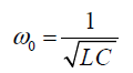 (1)
(1)
The ratio of these parameters is named quality factor Q which shows the quality of the stored energy in resonator:
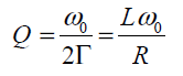 (2)
(2)
In order to increase efficiency, it is necessary to have a high quality factor. In the section six, the proposed design will be described more. Firstly, we should investigate the limitations.
Limitations
For designing a WPT charger for a DBS system there are some limitations that affect the choise of components. These limitations are according to the following:
• Distance
Although there isn’t any limitation for the maximum distance between the primary and secondary coils, its minimum distance should be the same as human skin’s thickness which is about 8 millimeters.
• Size
This structure should be small enough to be placed between the thorax and skin without making any trouble for patient, and in some cases the input voltage and the frequency have limitations too.
Proposed System
The main operation of this method in the physical theory is defined as the Coupled Mode Theory (CMT). This theory can be summarized in this manner: in multisectorial power system in which the parts are strongly coupled, some parts that are oscillating in the same frequency (resonance) are more trepanned than those parts which are just coupled (oscillating in different frequencies).
Modeling
The base of the operation is the same as usual transformers but without any ferrous or ferrite core. A layer of fat and skin will be placed between two coils (receiver and transformer coils). In order to reduce the effect of distance and to compensate the low magnetic coupling in receiver and transmitter coils, it is necessary to supply it in high frequency and the resonance frequency of the primary and secondary coils should be the same as the source frequency. So, matching networks are required in both coils.
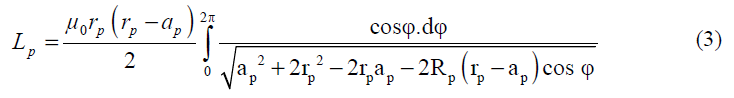
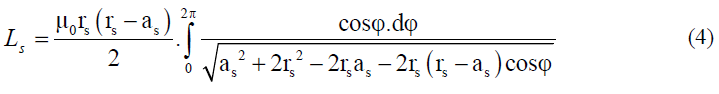
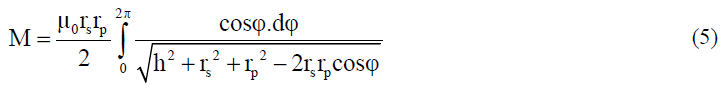
For two circle coils, the inductances in fig.7 are obtained using equations (3), (4) and (5) [14]:

Figure 7. General schematic of a WPT system
That Lp and Ls are the coil’s self-inductance, M is the coil’s mutual coupling, μ0 is the coefficient of magnetic permeability of the free space, rp and rs are the coil’s radius, h is the distance between two coils, and ap and as are the wire section’s radius.
Optimization
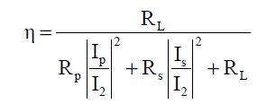
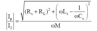
For matching the network in the secondary side a series or parallel capacitor can be used. Fig.8 shows this new system. Each of the compensatory methods changes the system’s electrical and behavioral features and in some cases a special method is the main priority. When the compensation in the secondary is in series, the output can be a constant voltage and when it is in parallel, the output can be a constant current [11-13].

Figure 8. A WPT system with a compensation series capacitor in the secondary side
Assuming the series capacitor in the secondary side and the lossless matching network in the primary side, the efficiency is:
 (6)
(6)
 (7)
(7)
 (8)
(8)
In equation (6), is the efficiency of the system, Rp is the
primary coil’s resistance, Rs is the secondary coil’s resistance
and RL is the load resistance. For maximum efficiency, based
on equations (6) to (8), Cs can be obtained as:
is the efficiency of the system, Rp is the
primary coil’s resistance, Rs is the secondary coil’s resistance
and RL is the load resistance. For maximum efficiency, based
on equations (6) to (8), Cs can be obtained as:
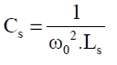 (9)
(9)
The impedance matching network for receiving and transforming the maximum power from the source and also reducing the voltage to current ratio of the source is placed in the input part. This network is designed by Smith chart diagram.
The impedance matching network for receiving and transforming the maximum power from the source and also reducing the voltage to current ratio of the source is placed in the input part. This network is designed by Smith chart diagram.
Simulation Results
To verify the the accurate operation of this system, it is designed for a 200Ω load and simulated by PSIM software. Fig. 9 shows the load's voltage.

Figure 9. The Simulation of the output voltage by PSIM for a 300Ω load resistance
Experiments
Fig. 10 and 11 show our experimental setup. In this setup, we used two boards for placing the elements, two LED's as the load and some cow's meat for simulating of the human body.

Figure 10. The photo of the proposed system

Figure 11. Wireless power transmission through the meat
Also, some experimantal results are shown in the next sections. Firstly, there is no distance between the primary and secondary coils and then this distance is increased by 1cm in every case. Fig.12 and table.1 show the output voltage and the results of the first test.

Figure 12. The Output voltage for zero distance case (Volt/div =10usec , Time/div= 2V)

Table 1. Results for no distance case
In the second test, the coils are 1cm away from each other. Fig.13 and table.2 show the output voltage and the results of this test, respectively.

Figure 13. The Output voltage for 1cm distance (Volt/div =10usec , Time/div= 2V)

Table 2. Results for 1cm distance
In the third test, the distance was increased by 1cm. Fig.14 and table.3 show the output voltage and the results of this test, respectively.

Figure 14. The Output voltage for 2cm distance (Volt/div =10usec , Time/div= 2V)

Table 3. Results for 2cm distance
In the last test, the distance was increased by 1cm more. Fig.15 and table.4 show the output voltage and the results of this test, respectively.

Figure 15. The Output voltage for 3cm distance (Volt/div =10usec , Time/div= 2V)

Table 4. Results for 3cm distance
Table. 5 shows a comparison between this work and other researches. All the systems in this table work based on the resonance inductive coupling results of this table, the system that is presented in this paper for short distance (8- 10mm), that is suitable for deep brain stimulators, have the best results (efficiency = 41.62% for d=10mm).

Table 5. Comparison between this paper and other researches
Conclusion
In this paper, a wireless power transmission system using the resonance inductive coupling (RIC) for charging a deep brain stimulator has been studied. As figures and results demonstrate, by increasing the distance, the output voltage and as it’s efficiency are decreased. In the human body, a layer of skin with fat has about 8mm thickness and in this distance the efficiency is more than 40%.
References
- DS. Kern, MS, and R. Kumar, MD, FRCPC, the Neurologist,Deep Brain Stimulation, September 2007.
- G.Wang, W. Liu, M. Sivaprakasam, M. Zhou, J. D.Weiland, and M. S. Humayun, “A dual band wireless power and data telemetry for retinal prosthesis,” in Proc. IEEE EMBS Conf., pp. 28–38., 2006.
- M. Niroomand, H. R. Karshenas, “Performance Specifications of Series-Parallel UPS’s with Different Control Strategies”, International Review of Electrical Engineering, IREE, February 2009.
- Olutola Jonah, Student Member, IEEE, and Stavros V. Georgakopoulos, Senior Member, IEEE, “Wireless Power Transfer in Concrete via Strongly Coupled Magnetic Resonance,” IEEE TRANSACTIONS ON ANTENNAS AND PROPAGATION, VOL. 61, NO. 3, 2013...
- A.Sample, D. Meyer, and J. Smith, “Analysis, experimental results and range adaptation of magnetically coupled resonators for wireless power transfer,” IEEE Trans. Ind. Electron., vol. 58, no. 2, pp. 544–554, Feb. 2011.
- T. P. Duong and J. Lee, “Experimental results of highefficiencyresonant coupling wireless power transfer using a variable coupling method,” IEEE Microw.Wireless Compon.Lett., vol. 21, no. 8, pp. 442–444, Aug. 2011.
- A.Kurs, A. Karalis, R. Moffatt, and M. Soljacic Marin, “Simultaneous midrange power transfer to multiple devices,” Appl. Phys. Lett., vol. 96, p. 044102, 2010.
- A M. Kiani and M. Ghovanloo, “An RFID-based closed-loop wireless power transmission system for biomedical applications,” IEEE Trans. Circuits Syst. II,Exp. Briefs, vol. 57, no. 4, pp. 260–264, Apr. 2010.
- H. Matsumoto, Y.Neba, K.Ishizaka, and RyozoItoh, Comparison of Characteristics on Planar Contactless Power Transfer Systems, June 2012.
- F. Jolani, J. Mehta, Y. Yu, and Z. Chen, Design of wireless power transfer systems using magnetic resonance coupling for implantable medical device, Progress In Electromagnetics Research Letters, Vol. 40, 141-151, 2013.
- R. Harrison, “Designing efficient inductive power links for implantable devices,” in Proc. ISCAS, pp. 2080–2083, 2007.
- Medtronic DBS Therapy Clinical Summary, 2009.
- SlavkaViteckova,PatrikKutilek, Marcel Jirina, "Wearable lower limb robotics: A review", Biocybernetics and Biomedical Engineering, Volume 33, Issue 2, 2013.
- Akin OguzKapti, GulcinMuhurcu, "Wearable acceleration sensor application in unilateral trans-tibialamputation prostheses", Biocybernetics and Biomedical Engineering, Volume 34, Issue 1, 2014.
- M. Niroomand, H. R. Karshenas, “A Hybrid Learning Control Strategy for Three-Phase UPS,” The Institute of Engineering and Technology, IET, 799-807, Aug 2011.
- O. H. Stielau and G. A. Covic, “Design of loosely coupled inductive power transfer systems,” in Proc. Int. Conf. Power System Technology, vol. 1, Dec. 2000, pp. 85–90.
- Ch.Wang, Oskar H. Stielau, and Grant A. Covic, "Design considerations for a contactless electric vehicle battery charger," IEEE Transactions on industrial electronics, vol.52, No.5, October 2005.
- A.K. RamRakhyani, S. Mirabbasi, and M. Chiao, “Design and optimization of resonance-based efficient wireless power delivery systems for biomedical implants,” IEEE Trans. Biomed. Circuits Syst., vol. 5, no. 1, pp. 48–63, Feb. 2011.
- Sh.Goma, Murata Taps Capacitive-Coupled Method forwireless power transfer, AEI November 2011
- C. Zierhofer and E. Hochmair, “Geometric approach for coupling enhancement of magnetically coupled coils,” IEEE Trans. Biomed. Eng., vol. 43, no. 7, pp. 708–714, Jul. 1996.
- U.M. Jow and M. Ghovanloo, “Design and optimization of printed spiral coils for efficient transcutaneous inductive power transmission,” IEEE Trans. Biomed. Circuits Syst., vol. 1, no. 3, pp. 193–202, Sep. 2007.