ISSN: 0970-938X (Print) | 0976-1683 (Electronic)
Biomedical Research
An International Journal of Medical Sciences
Research Article - Biomedical Research (2017) Volume 28, Issue 8
Biomechanical analysis of electric powered wheelchair by reverse engineering modelling technology
Wheelchair technology is one of the most significant technologies in biomechanics sector. The demand of Electric Powered Wheelchairs (EPWs) has been increasing due to improving the lifestyles of patients suffering from one or more disabilities, including motor control problems, spinal injuries, arthritis, balance disorders and amputation under the term of rehabilitation technologies. Hence, the healthcare research has made several plans for improving control of EPW to provide well-being, and safety by minimal cost. On the other hand, Reserve Engineering (RE) is a powerful technique for creating a new model to uncover the features of commercial products and enhance them. As such, we applied RE to develop a functional model through teardowns that designed by SolidWorks 3D Computer Aided Design (CAD) software to provide the full specifications of EPW. Moreover, we implemented an Arduino microcontroller to change the EPW directionality by using a joystick. This model evaluates the flexibility and wireless control of EPW by adding further improvements such as an ultrasonic sensor and Bluetooth connection. Ultrasonic sensor acts as an emergency stop switch to notify the patient when roaming close to an obstacle as a safety precaution. Bluetooth connection device allows the patient to remotely control the electric wheelchair if it was out of reach or there’s no one close to assist. The main characteristic of our model is mobility performance without depending on others’ help that based on an affordable cost.
Keywords
Electric powered wheelchairs, Rehabilitation, Reserve engineering, SolidWorks, Computer aided design.
Introduction
Improved wheelchair mobility could be an important factor in realizing increased independence for patients unable to walk. It attempts to restore human abilities that have been reduced or lost by disease, accident or aging [1]. Manual wheelchairs can be operated by patients who have the use of their upper body or someone available to assist [2]. EPWs have been developed to be used when neither of these cases is available. However, there have been few advances made with EPW due to lack of a high level of user control thus it can result in injury to the patient during the EPW operating process.
The capability of patients to push their own wheelchair successfully is affected by three main factors: patient characteristics (e.g. type and degree of disability, patient dimensions, patient weight and patient age), wheelchair properties (e.g. size and weight of wheelchair, size and type of wheels and tires, axle position, backrest height and use of armrests), and wheelchair/patient interface (e.g. patient adapt and adjust of the chair for patient). The most basic task of the chair is to take input from the patient, usually in the form of a small joystick and translate that motion into power to the wheels to move in the desired direction. The earliest research by Beekman [3] explained that patients with paraplegia and tetraplegia have the ability of mobility readily by using lightweight wheelchairs instead of standard wheelchairs. Brown et al. [4] presented a model for PID controller implemented on a microprocessor, which is used for joystick controllers of EPWs. This model lacks stability. Furthermore, it is an inappropriate for wheelchair's motion changes.
In recent decades, many biomechanical studies have discussed the possibilities of EPW to improve the stability and mobility of handicapped patients who are too weak to propel themselves [5,6]. Rentschler et al. [7] discussed five types of EPW which included three Rear Wheel Drive (RWD), one Mid-Wheel Drive (MWD) and one Front Wheel Drive (FWD). These were implemented on set of experiments which provided an important influence on moving with stability and safety.
Wheelchairs that based on renewable energy systems (batteries and solar panels) have been studied in another research [8], in which solar panels have been found to be employed as a good and cheap source of energy. However, the time taken to charge the chair was an obstacle. If chair charge need to be increased, many number of panels needed to be fitted resulted in increasing the wheelchair weight. Humaira et al. [9] produced a successful prototype of an Electric Wheelchair (EWC) of US $ 400, while the minimum cost of EWC was around US$ 1100 in USA. In this prototype, a 40-pin PIC18F4520 microcontroller was used to secure EWCs movement in the required direction after received a signal from the joystick. Information gathered [10] was purposed to raise awareness of wheelchair technology and improve the performance of patient who relied on EPW. Moreover, it enhanced many parameters such as velocity, traction, suspension, stability, and navigation.
Due to advances of computerized technology, Ambient Company has developed a device for intercepted electrical signals sent by brain to larynx in an attempt to speak [11]. It was used as a guide for wheelchair, and enables patients to cross without moving or speaking loudly. Ambient was used in the Rehabilitation Institute of Chicago to support patients with nervous system problems by computer and electronic devices regardless of their inability of muscle control.
Generally, RE technique [12] is used as a learning tool to disassemble, examine and analyse the product or device for reproducing with different mechanisms. In addition, it discovers the concepts involved in manufacture in order to produce something similar. The process of RE is a three-phase process that includes scanning, point processing, and application geometric development. CAD models generation within RE is required to produce the accurate representation by three-dimensional reconstruction. Additionally, its arrangement is stable and has less error of data transfer formats [13]. Yu [14] focused on the engineering application of RE based on measurement machine and CAD software. Recently, the powerful RE technique is used for modelling the biostructures in the mechanical analysis. Thus, building comprehensive developments for biomechanical analysis, particularly for prostheses framework [15].
The outstanding progresses in rehabilitation field have created excitement about EPW manufacture now and for the future. Therefore, this study used the 3D CAD which had been constructed by means of RE technique to design new and compatible wheelchairs. The latest is cheaper than that currently used. We developed an affordable device with advanced features based on moving in different directions easily. All connections between motors, microcontroller and joystick were introduced.
Materials and Methods
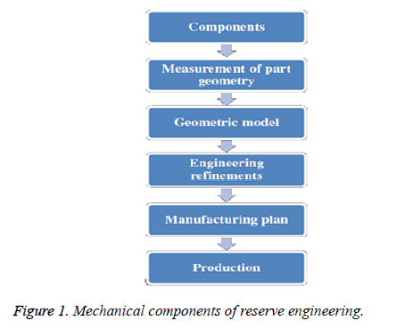
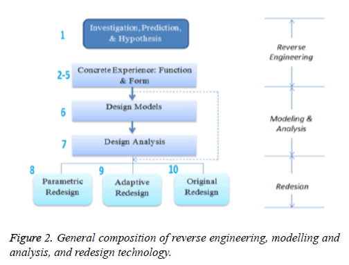
The model of EPW was applied with RE by using CAD program and mechanical systems. An example of CAD program is SolidWorks software [16], which provides detailed drawings that are manually fed to the computer. According to a lightweight wheelchair structure, this model was designed to carry a disabled person with maximum 100 Kilograms (Kg) including equipment and body weight. Figure 1 explained the RE mechanical components. RE modelling and analysis, and redesign [17] as shown in Figure 2. The first phase is divided in five steps; the first step includes investigation, prediction, and hypothesis. The second step is concrete experience, the third step is function, the forth step is engineering constraint and the fifth step is characterizations form. The main objectives of the first phase are treating, experiencing the operating factors, analysing the customer needs and deducing product components. The second phase is based on two steps including, design models and design analysis that is used to development, analysis, calibration, and experimentation of model. The third phase is based on the product redesign from the results of the RE and modelling phases. Redesign phase consists of a parametric redesign that is used for optimization analysis of the design models, an adaptive redesign that is used product components and subassemblies and original redesign that is needed to fulfil the customer needs. Functional analysis step from the RE phase is directed to the redesign phase.
Experimental work
Drive wheel motor torque: We assumed the model criteria as shown in Table 1.
| Parameters | Value |
|---|---|
| Gross Vehicle Weight (GVW) | 300 Kg |
| Weight on each drive wheel (WW) | 4.5 Kg |
| Radius of wheel/tire (Rw) | 0.1 m |
| Desired top speed (Vmax) | 0.25 m/s |
| Desired acceleration time (ta) | 1 sec |
| Maximum incline angle (a) | 20 degree |
| Worst working surface | Sand (good) |
| Resistance Factor (RF) | 1.3 |
Table 1. Vehicle design criteria.
The RF is resistance factor that accounts frictional losses between bearings and axles. Standard values are between 1.1 and 1.15. There are many factors that affected on calculation of maximum torque [18,19] such as the following.
1) Rolling Resistance (RR): is based on vehicle weight and rolling resistance factor during motion of the vehicle as in Equation 1.
RR [lb]=GVW [lb] × Crr [-] → (1)
where Crr=surface friction as shown in Table 2.
| Contact surface | Crr |
|---|---|
| Concrete (good/fair/poor) | 0.010/0.015/0.020 |
| Asphalt (good/fair/poor) | 0.012/0.017/0.022 |
| Wood (dry’ dusty wet) | 0.01/0.005/0.001 |
| Snow (2 inch/4 inch) | 0.025/0.037 |
| Dirt (smooth/sandy) | 0.025/0.037 |
| Mud (firm/medium/soft) | 0.037/0.090/0.150 |
| Grass (firm/soft) | 0.55/0.075 |
| Sand (firm/soft/dune) | 0.060/0.150/0.300 |
Table 2. Rolling resistance factors.
Grade resistance (GR): is based on gravitational force that used to drag the vehicle back when it is scaling an oblique surface as in Equation 2.
GR [lb]=GVW [lb] × sin (α) → (2)
2) Acceleration force (FA): is based on needed force to stop the maximum speed in the required time as in Equation 3.
FA [lb]=GVW [lb] × Vmax [ft/s]/(32.2 [ft/s2] × ta [s]) → (3)
3) Total tractive effort (TTE): is based on three forces RR, GR, and FA as in Equation 4.
TTE [lb]=RR [lb]+GR [lb]+FA [lb] → (4)
4) Wheel motor torque (Tw): is based on the TTE as in Equation 5.
Tw [lb-in]=TTE [lb] × Rw [in] × RF [-] → (5)
Mechanical and electrical equipment
The EPW is moved via an electric DC motor and a navigational control system which consists of a small joystick mounted on the armrest, rather than manual one. It is designed by two major components, the power base containing two DC motors, wheels, and a control module. For this work, some of the electrical and electronic components are briefly described as follows:
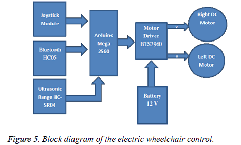
• Arduino mega 2560: it is a microcontroller board based on the ATmega1280. It has 54 input pins, 15 output by Pulse Wave Modulation (PWM). It has 128 KB of flash memory, and 8 KB of static random access memory. All features of this microcontroller board are explained in [20].
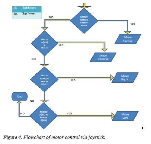
• Analog joystick module (4 Directions): It is a physical device that used to control in movement. It needs to determine the angle and direction on two axes: -X-axis and Y-axis. X-axis refers to left and right directions but Y-axis refers to up and down directions. The Analog joystick consists of a momentary push button and two potentiometers. Speed values of joystick are between 0 and 1023 and threshold values are between 462 and 562 as in Figure 3. Figure 4 explained the flow chart of motor control by using Joystick.
• Motor driver BTS7960 43A: it has a voltage of 24 V and a current of 43 A. It requires a high amount of current which bridges for motor drive control, especially for controlling a high power motor such as the MY1016Z2 DC motor that used to Maneuver the electric wheelchair. The main specifications of the motor driver are illustrated in [21]. The motor driver is used an H-Bridge [22] as the main concept of operation to control the DC motors.
• DC motor: it is a device which converts electrical energy into mechanical energy. DC motor used in this model is the MY1016Z2-250W DC motor manufactured by Yeuqing Instruments. The specifications of the motor are given in [23]. This motor improved the efficiency, save power and its price is low.
• Ultrasonic range HC-SR04: it extends to range 2 cm-400 cm and accuracy can reach to 3 mm. This device includes ultrasonic transmitters, receiver, and control unit. Ultrasonic sensors evaluate the execution time between sending the signal and receiving the echo to calculate the distance to an object [24].
• Bluetooth-HC05-module: it is a wireless device for exchanging data over short distances from mobile devices, and building Personal Area Networks (PANs). It provides range of 10 meters. It is widely used for wireless network such as GPS device, and remote control. It consists of radio, memory chips, 26 MHz crystal, and antenna as in [25].
• Fan speed controlled by temperature and arduino: it is used for monitoring the DC fan speed depending on the temperature reading by an LM35 sensor. The LM35 is precision integrated-circuit calibrated directly in degree Celsius. Its linear scale factor+10 mV/°C. Its ensured accuracy is 0.1 degree Celsius. This will make it as an advantage over linear temperature. It is rated from -50°C to +150°C. A Liquid Crystal Display (LCD) shield is used to show the temperature and speed of the fan. In this model, the BD139 transistor, and a 9 V battery are utilized. The LM35 temperature sensor and red led are provided with 5 V from the microcontroller board. A configuration circuit for fan speed controller by temperature and Arduino is described in [26].
The block diagram of our model which is composed of all the components listed earlier is given in Figure 5.
Results
From the above calculation of mechanical parts by using Equations 1-5, we found that TW equals 322 N. M and torque of each wheel is 200 N. m approximately (2000 Kg/cm-1). We used the concept of RE technology and all vehicle design parameters for modelling the EPW. The design of our model is presented by 3D SolidWorks mechanical design automation software which is used parametric characteristics for producing synthesis model. Parameters indicated to the values for definition the form of the model. Parameters divided into numeric parameters (e.g. line length, circle diameter) and geometric parameters (e.g. tangent, parallel, concentric, horizontal, and vertical). Numeric parameters are linked to geometric parameters by different relations, which allowed them to complete the required design.
In our work, we measured distance, angle, and size of between lines, points and surfaces by calliper and meter. After taking measurements of the chair, we have entered the measured data in SolidWorks.
Here the most instructions in SolidWorks for design:
1) Sweep: create model shape by moving a 2D design profile along a 2D or 3D design path. There are different options of this powerful feature.
2) Fillet: create rounded external or internal faces on the parts.
3) Extrude cut: is another cool feature which helps to remove material from a 3D model.
4) The circular pattern: property manager appears when the user pattern one or more features around an axis.
5) Mirroring features: this ability is found at part level and creates a copy of one or more features mirrored about a face or a plane.
6) An assembly design: consists of some assembled components by using parametric relations. In SolidWorks, these relations are known as mates that provided the dealing with components freely.
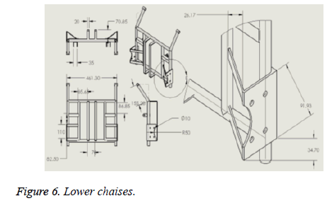
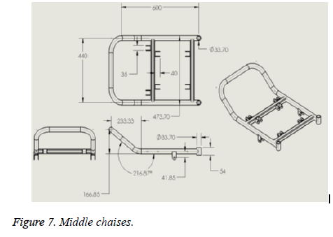
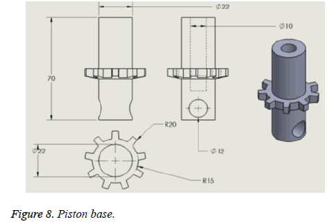
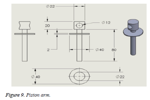
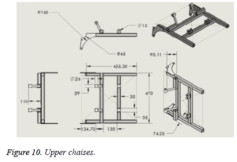
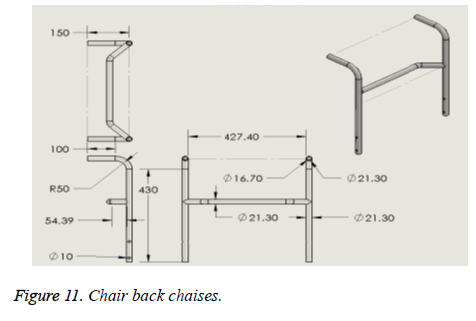
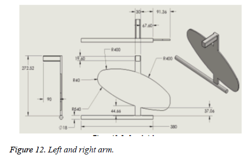
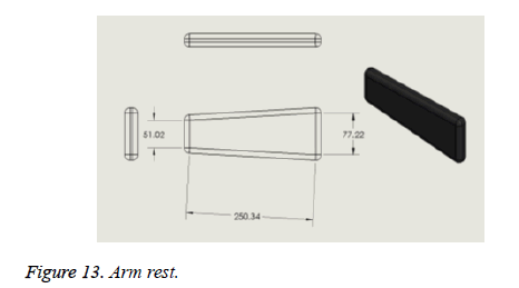
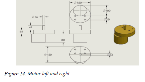
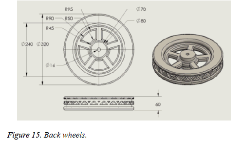
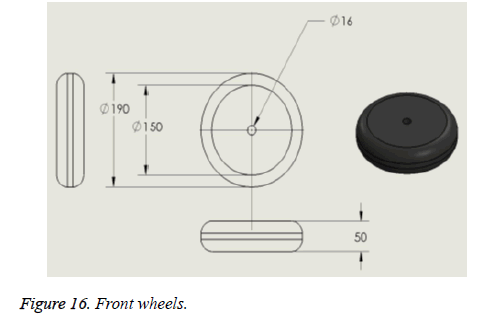
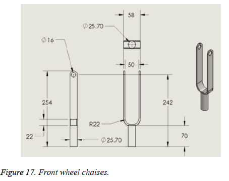
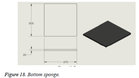
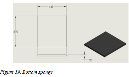
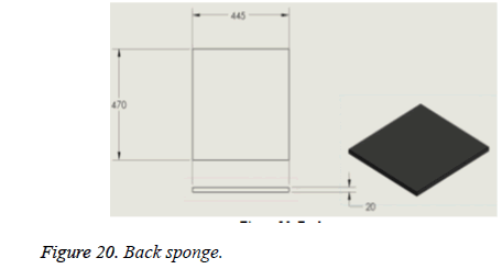
We presented details of implementation stages by using SolidWorks in Figures 6-20.
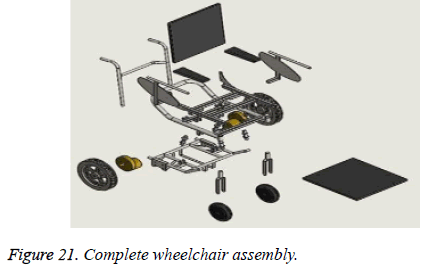
Figure 21 showed the complete wheelchair assembly. All wheelchair specifications are given in Table 3.
| Description | Measurements |
|---|---|
| Seat width | 47 cm |
| Neat depth | 46 cm |
| Armrest height | 25 cm |
| Seat height | 48 cm |
| Back height | 46 cm |
| Overall open width | 65 cm |
| Overall length | 80 cm |
| Weight w/o | 55Kg |
| Weight capacity | 140 kg |
| Rear wheel size | 31 cm |
| Front wheel size | 19 cm |
| Footrests height | 10 cm |
Table 3. Technical specifications of the model.
The mechanical and electrical components that were used to build this model incurred a cost as in Table 4. It should be noted that our model costs 5675 EGP (nearly US$ 600), which is less than commercially available price at US$ 1100. The comparison between the EPWs from different manufacturers that already used in Egypt market is given in Table 5.
| Description | Category | Quantity | Price |
|---|---|---|---|
| Rear wheels | Mechanical | 2 | 1000 |
| Front wheels | Mechanical | 2 | 200 |
| DC motors 24 V | Electronic | 2 | 1500 |
| Chair skeleton | Electronic | 1 | 300 |
| Intelligent battery charger | Electronic | 1 | 200 |
| Tablet | Electronic | 1 | 400 |
| Wires+Cables | Electronic | - | 50 |
| Battery (12 V) | Electronic | 2 | 920 |
| Digital ultrasonic module for Arduino | Electronic | 2 | 60 |
| DC motor driver | Electronic | 2 | 300 |
| Arduino Mega 2560 | Electronic | 1 | 370 |
| Bluetooth HC-05 | Electronic | 1 | 75 |
| Model joystick 4 direction | Electronic | 1 | 50 |
| Board components | Electronic | 250 | |
| Total cost | 5675 EGP | 5675 EGP |
Table 4. Parts list and cost of the model.
| Type | Spare parts | Price (EGP) |
|---|---|---|
| Egypt | Non | 7,000 |
| China | Available | 8,000 |
| Taiwan | Non | 9,000 |
| Korea | Non | P,000 |
| Germany | Available | 15,000 |
Table 5. Comparison between the EPW Prices in Egypt.
Discussion
Because of the market potential and rapid advances in biomechanics, notable progress is being made in wheelchairs. The EPW evaluation is based on the quality, safety, and costeffectiveness of wheelchairs. Efficient EPW model with a low cost is presented. Our EPW model is distinguished from most other similar EPW in its attempts to use practical components for minimizing maintenance concerns through simplicity and durability.
Overall, this model consists of software and hardware interface parts. SolidWorks designing software was established to build 3D CAD model with full specifications of EPW by using RE technology. The implementation of RE technology allowed reusing past data for design composition model [27]. It facilitates analysis of the model that based on historical product data and produces practical developments during product assembly procedures. For example, General Motors Company have vehicles assessment center that dissected and analysed 40 of rivals’ vehicles every year by using a “teardown” process [28] to learn how much each component costs for producing, how to achieve lower costs, and how to progress industrialization process. By using RE technology, marketplace trends and competitiveness can be defined. This technology extended to product teardowns of mechanical and electronics as shown in our model.
For hardware parts, the core of this model is the Arduino Mega 2560 microcontroller which is also capable of functioning as a micro web server and the interface for all the hardware parts [29]. A microcontroller is controlled by DC motors for transmission in all directions or to stop by using a joystick. All communication and controls in this model passed through this microcontroller effectively. A recent development controlled EPW was implemented using the Bluetooth device and ultrasonic sensor. Bluetooth device is used for wireless control of the electric wheelchair and enables it to work as a standalone device. We have used two ultrasonic sensors that stable at a known distance. Speed of the object is estimated by divided the distance between the two sensors by the time difference of the object. The ultrasonic sensor is designed for easy usage and much cheaper with outstanding performance, especially in an automated device.
Another interesting feature is control of components temperature. The temperature of electrical components is affected by the ambient temperature of the environment, the heat produced by the components, and the efficiency of heat removal provided by the thermal system. Component temperature can be decreased by improving any of these factors. Based on fan Speed controlled by temperature, more efficient component gives off less heat and the advanced thermal system is capable of quickly removing heat.
Finally, disabled patients are challenged for operating the EPW in different environments. Hence, the EPW designed in this model is a successful electronic device that provided for patients the ability to recover part of their mobility and ease the lives of patients suffering from one or more disabilities. It is certainly important to continue to implement appropriate biomechanical advances of EPW in order to improve the health and benefit of a patient with disabilities.
Conclusion
Based on the principles of RE technology, we applied RE technology in the design and manufacturing of EPW by using SolidWorks 3D CAD. EPWs have improved the quality of life for many patients with physical disabilities through the mobility they provide. The EPW acts as a good bio-test for mechanical and electrical integration packages due to the compact and multifaceted nature of the vehicle. The cost of EPW manufacturing processes is increasing rapidly, for which many patients might not be able to afford the rising costs. This paper discussed how both electrical and mechanical implementations have turned the wheelchair into a smart and adaptive vehicle with a low cost. It also examined the most recent advances in EPW technology by using Bluetooth and ultrasonic sensor. Moreover, this model may be a guide for future trends to enhance the rehabilitative and assistive needs of patients. It would be interesting to redevelop of EPWs technology to give patients access to perform the daily tests with themselves easily.
References
- Rafidah R, Afiqah Y, Norashikin MT, Jamilah K. Design and development of electrical powered wheelchair model for navigation control. IEEE SympIndustrElectrAppl 2011; 675-680.
- Boninger ML, Baldwin M, Cooper RA, Koontz A, Chan L. Manual wheelchair pushrim biomechanics and axle position. Arch Phys Med Rehabil 2000; 81: 608-613.
- Beekham CE, Miller-Porter L, Schoneberger M. Energy cost of propulsion in standard and lightweight wheelchairs in people with spinal cord injuries. PhysTherap 1999; 79: 146-158.
- Brown KE, Inigo RM, Johnson BW. Design, implementation, and testing of an adaptable optimal controller for an electric wheelchair. IEEE Trans IndustrAppl 1990; 26: 1144-1157.
- Tan YK, Sasidhar S. Engineering better electric powered wheelchairs to enhancerehabilitative and assistive needs of disabled and aged populations, rehabilitation engineering. Tan Yen Kheng INTECH Singap 2009; 79-108.
- Cooper RA, Boninger ML, Spaeth DM, Ding D, Guo S, Koontz AM, Fitzgerald SG, Cooper R, Kelleher A, Collins DM. Engineering better wheelchairs to enhance community participation. IEEE Trans Neur Sys Rehab Eng 2006; 14: 438-155.
- Rentschler AJ, Cooper RA, Fitzgerald SG, Boninger ML, Guo S, Ammer WA, Vitek M, Algood D. Evaluation of selected electric-powered wheelchairs using the ANSI/RESNA standards. Arch Phys Med Rehab 2004; 85: 611-619.
- Arvind P, Snehal S, Priyanka R, Ashish S. Powered wheelchairs. Int J SciTechnol Res 2013; 2.
- Humaira S, Hafiz R, Pratik KK, Fahmid JSBM,Nasiruzzaman KBM, Rahman MDM. Design and implementation of an electric wheel-chair to economize it with respect to Bangladesh. Int J MultidisciplSciEng 2014; 5.
- Ding D, Cooper RA. Electric powered wheelchairs. IEEE Cont Sys Magaz 2005; 25: 22-34.
- Ambient Corporations, New Human-Computer Interface called Audeo Intercepts Words When Thought, 2007.
- Thompson WB, Owens JC, de St HJ. Germain, featured-based reverse engineering of mechanical parts. IEEE Trans RobotAutom 1999; 15: 57-66.
- Sun WBS, Nam J, Darling A. Bio-CAD modelling and its applications in computer aided tissue engineering, computer-aided design. Elsevier 2005; 37: 970- 1114.
- Zhang Y. Research into the engineering application of reverse engineering technology. JMater ProcTechnol Elsevier Sci 2003; 139: 472-475.
- LatifAghili A, Goudarzi AM, Hojjati MH, Rabiee SM, Misagh I, Ali P. Biomechanical investigation of human femur by reverse engineering as a robust method and applied simplifications. W ApplSci J2013; 28: 2152-2157.
- SolidWorks software: https://www.solidworks.com/sw/3d-cad-design-software.htm
- Otto K, Wood K. A reverse engineering and redesign methodology for product evolution. Proc ASME Design Theory MethodolConf 1996.
- Hibbeler RC. Engineering mechanics: statics and dynamics. Pearson Prentice Hall (11th edn.) 2007; 441-442.
- Rony A. The electric vehicle, technical report. Santa Barbara CollEngUnivMar. 2010.
- Arduino Mega 2560: https://www.arduino.cc/en/Main/ArduinoBoardMega.
- Motor Driver BTS7960 43A: http://www.instructables.com/id/Motor-Driver-BTS7960-43A/
- Manjunath BR, Chakrasali RL. Speed-torque characteristic of dc motor fed by h-bridge converter. Int J Energ Power2014; 3: 49-53.
- Bature AA, Mustapha M, Auwalu MA. Parameter identification of a class of dc motor. Int J ResEngSci2013; 1: 69-72.
- Ultrasonic Range HC-SR04: http://randomnerdtutorials.com/complete-guide-for-ultrasonic-sensor-hc-sr04/
- Bluetooth-HC05-Module:https://arduino-info.wikispaces.com/BlueTooth-HC05-HC06 Modules-How-To?responseToken=05c18a8b1549720cec433fac0c91e8bfc
- Fan Speed Controlled by Temperature and Arduino: http://www.electroschematics.com/9540/arduino-fan-speed-controlled-temperature/
- Otto K, Wood K. Product design: techniques in reverse engineering and new product design. Prentice Hall 2001.
- Hoffman C. The teardown artists. Wired 2006; 136.
- Nathan D, Abafor C, Aronu U, Edoga O. Design of a home automation system using Arduino. Int JSciEng Res2015; 6: 795-803.
