ISSN: 0970-938X (Print) | 0976-1683 (Electronic)
Biomedical Research
An International Journal of Medical Sciences
Research Article - Biomedical Research (2018) Artificial Intelligent Techniques for Bio Medical Signal Processing: Edition-II
Research on the signal of 4He pump magnetometer sensor using ECDL laser
Wang Chao1,2, Zhou Zhijian1,2* and Cheng Defu1,2
1College of Instrumentation and Electrical Engineering Jilin University Changchun, Jilin, PR China
2Key Laboratory of Geo-Exploration Instruments Ministry of Education of China Changchun, Jilin, PR China
- *Corresponding Author:
- Zhou zhijian
College of Instrumentation and Electrical Engineering
Jilin University, PR China
Accepted date: June 19, 2017
DOI: 10.4066/biomedicalresearch.29-17-752
Visit for more related articles at Biomedical ResearchOne of the most important factors determines specifications of 4He optically pumped magnetometer is the quality of resonance signal given by sensor probe. This paper introduces a laser 4He optically pumped magnetometer using an ECDL laser. An external cavity length tuning system of ECDL laser based on the double light path atom saturated absorption spectrum method with a 4He cell is build up to ensure that an effective 1083.207 nm laser light source is provided for the magnetometer probe. It is designed a double path photoelectric detector to get the absorption peak signal by the difference technology. Because signal in accordance with Lorentz linear features, a detection method combined with first and second derivative of signal curve is proposed. Join a modulation signal whose form is dc component add sinusoidal component, the system make ECDL laser give a stable output wavelength around 1083.207 nm. With the laser light, a resonance signal with better quality than the 4He optically pumped magnetometer probe using the gas discharge lamp light source is given.
Keywords
4He optically pump magnetometer, Resonance signal, Lorentz linear, ECDL, Modulation signal
Introduction
Magnetic field and the human life is closely linked, in ancient China, one of the four great inventions-compass, is based on the magnetic field to realize the north and south [1,2]. With the development of science, the effect of magnetic field cognition by people gradually, it is not only can detect the earth's resources, also can be used for military anti-submarine and predict earthquakes, even play an important role in biomedical [3]. Based on this reason, the development of the magnetic field measurement technology is very rapid, play an important role in multiple disciplines [4].
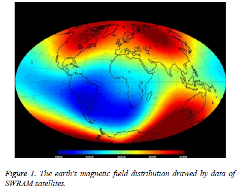
There are many kinds of magnetic field measuring methods, optically pumped magnetometer is one of the most widely used instrument. Particularly, three satellites of SWRAM space exploration program launched by ESA (European space agency) in 2013 carried helium optically pumped magnetometer with a high sensitivity of 1pT/Hz1/2 and the ability to accurately drawed magnetic field scale. The earth's magnetic field distribution drawed by data of SWRAM satellites is showed in Figure 1. The SWRAM space exploration program shows us the broad space for development of 4He optically pump magnetometer [5]. Meanwhile, along with the progress of the theory of optical and laser technology, magnetometer is developing towards to a direction of alloptically.
4He Optically Pump Magnetometer Review
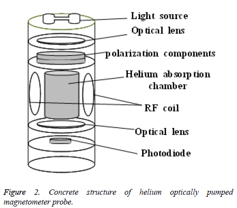
Briefly, helium optically pumped magnetometer is a magnetic measuring instrument with high sensitivity on the basis of Zeeman effect of helium atoms in the magnetic field and using optical pump function and Magnetic Resonance (NMR) function. The conventional helium pump magnetic probe is mainly composed of two sets of devices-devices related to the action of the optical pump and devices related to magnetic resonance, specifically, include a light source, a helium absorption chamber and an excitation system thereof, and lens, polarization components, an RF coil. In the helium pump magnetometer probe also includes the photodiode and its photoelectric conversion circuit. The concrete structure of magnetometer probe is showed in Figure 2. Optically pumped magnetometer complete magnetic field measurement by sensing the intensity changes of optical signal.
With the action of light source and sweep signal from RF coil, we refer to the output signal of the probe as the resonance curve. Usually, we calculate the sensitivity of the 4He optically pump magnetometer by Equation 1
δB=1/γHe × Δf/S⁄N → (1)
Δf is the Line width of resonance signal, it is defined as the difference of abscissa corresponds to the maximum and minimum value of resonance curve’s slope and S⁄N is the signal to noise ratio of resonance curve.
Through the Equation 1, we can get the conclusion that the quality of resonant signal given by probe is the most important factors of magnetometer. Traditional helium optically pumped magnetometer has a gas discharge lamp as a light source, we know, the stability and intensity of the light source affect the quality of the resonant signal, one of the important conditions to insure the sensitivity of magnetometer is the stabilized wavelength of pump optical [6]. Because of these requirements, laser is the best choice for light source.
This paper designs an external cavity length tuning system include the laser light source and optical path of saturated absorption spectrum to give a laser light wavelength around 1083.207 nm which 4He optically pump magnetometer wants [7]. Because one of the 4He absorption lines needs a 1083.207 nm light, so the saturated absorption spectrum device is based on a 4He cell. The tuning system uses a single chip processor as the controller, with phase sensitive detector to achieve the wavelength stabilization.
Cavity Length Tuning Experimental System
As we know, resonance cavity length plays the leading role to determine the output signal power and wavelength of laser diode [8]. Aimed at the shortcomings that inner cavity length of laser diode is too short, this paper chooses an ECDL laser, namely the external cavity semiconductor lasers. We placed a grating connected the PZT (piezoelectric ceramic) and the ZOM (laser diode emission head), the small piece of space between the two elements, called external cavity. The external cavity can cover the shortage of short internal cavity [9]. We can change the withstand voltage of PZT to make it put up a weak deformation to fine tune the length of external cavity [10], further, to tune the wavelength in the precise control.
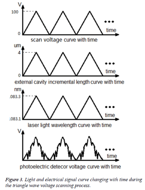
We summarize the process of the external cavity length tuning as follows: the voltage tuning components provide a periodic scanning signal that is a triangle wave, and its voltage range from 0 V to 100 V. Under the control of scanning signal, PZT has a periodic deformation with time, also the incremental length of the external cavity has a periodic change with time, the range of 0 μm to 4 m. Length of external cavity determines the wavelength of light has a range from around 1083.1 nm to around 1083.3 nm. As mentioned above, 4He atomic energy level transition between the meta-state and excited-state obtain energy through the absorption of light in the certain wavelengths [11]. Because of optical pumping action, there are three transitions during wavelength range of 1083.1 nm around to 1083.3 nm around, form the transition line D0, D1 and D2, respectively [12]. Part of the light and electrical signal curve changing with time during the voltage scanning process can be showed in Figure 3.
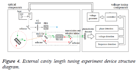
We set up an external cavity length tuning experiment system showed in Figure 4. We divided system into optical components and voltage tuning components. Laser light vertically into the λ/2 mirror through the direction adjust by the reflector mirror. λ/2 mirror can transform the laser light into the synthesis of vertical and horizontal polarization light [13]. λ/2 mirror can be rotating to control the energy of the two kinds of polarized light. PBS (Polarizing Beam Splitter) divides two kinds of polarized light. Vertical polarization light through the PBS, drawing as a blue arrow line in Figure 4 is used by the 4He pump magnetometer. Horizontal polarization light has a direction change of 90, drawing as a green arrow line in Figure 4 is used by the saturated absorption spectrum method.
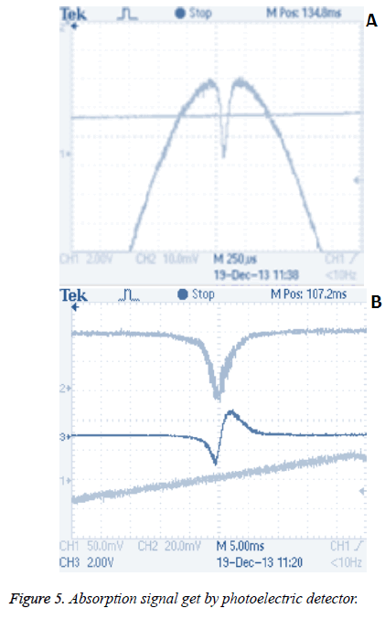
Optical path of saturated absorption spectrum method is showed in the dotted box of Figure 4. Horizontal polarization light divided into one transmitted light drawing as a red arrow line and two reflected lights drawing as two green arrow lines by thick flat mirror, the change is showed in the red dotted box of Figure 4. Since the optical pumping action mentioned above, two reflected lights would cause the phenomenon of absorption spectrum in the 4He cell. One transmitted light would enter the 4He cell with the effect of reflector mirror and could also cause the phenomenon of absorption spectrum, since it access into an opposite direction and registration with one reflected light, we can get an opposite absorption signal registration with the normal absorption signal by the photoelectric detector. Absorption signal get by photoelectric detector showed in Figure 5. Figure 5a shows the saturated absorption spectrum signal of the bidirectional light, Figure 5b shows the difference output of photoelectric detector.
Cavity Length Tuning Method
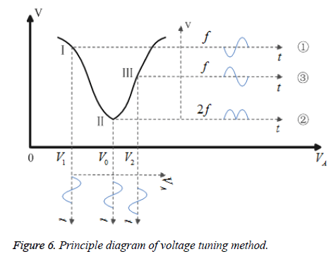
It is shall to lock the minimum point of curve showed as the blue curve in Figure 5b. Designed a voltage tuning method as follow: drawing the signal curve of Figure 5b in Figure 6, horizontal axis VA is the voltage value to PZT, vertical axis V is the voltage value of photoelectric detector. We set the tuning voltage signal as a dc component add sinusoidal component, VA=VX+VY × sin (2πft). Combining with Figure 6, assuming that the voltage value of minimum point is V0, when the tuning voltage VA<V0, the photoelectric detector signal has 180 phase difference to VA. Phase sensitive detector give a dc load voltage output to control the integrator improve tuning voltage, showed as curve in Figure 6. When tuning voltage VA>V0, the photoelectric detector signal has 0 phase difference to VA. Phase sensitive detector give a dc positive voltage output to control the integrator reduce tuning voltage, showed as curve ② in Figure 6. When tuning voltage VA around V0, the frequency of photoelectric detector signal is twice as large as tuning voltage signal, showed as curve ③ in Figure 5. So we can lock the area around the minimum point.
Curve of difference signal by photo-electric detector is a Lorentz linear [14]. Now, we could have description for locking the minimum point of a Lorentz linear signal with a tuning voltage to our job. First, calculate the first and second derivative of Lorentz linear, we found that when the Lorentz linear has the minimum point, its first derivative has a zero point, at the same time, its second derivative has the maximum points. After locking the area around minimum point of difference signal, we do precise locking in this way.
Signal of Laser Magnetometer Probe
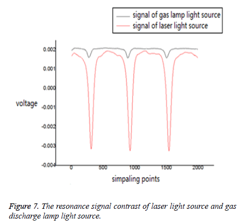
We can stable output laser light whose wavelength around 1083.207 nm with an accurate to 10-5 nm according to the 1083.207 nm ECDL laser external cavity length tuning experiment system and the tuning method above mentioned. We believe that using of the laser instead of the traditional gas discharge lamp can improve the quality of sensor probre’s resonance signal in theory. In order to verify this speculation, this paper designed the following experiment. First of all, use an electromagnetic shielding tube to build an electromagnetic environment without external magnetic interference. After that, place a Helmholtz coil in the electromagnetic shield tube, place the sensor probe in the uniform area of the coil and adjust the direction to ensure that it is not in the measured dead zone angle range. Finally, the use of high-precision controllable constant current source to ensure the Helmholtz coil in the electromagnetic shielding tube to produce a stable magnetic field. Respectively, the gas discharge light source and 1083.207 nm laser light source accessed into probe, the actual resonance signal can be got by the signal acquisition card. The resonant signals of the two light sources are shown in Figure 7. By contrast, we can get a conclusion that, the resonant signal amplitude increased by about 20 times without the increase of resonant line width.
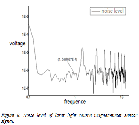
We can calculate the magnetic field value of resonant line width is around 350 nT divided by helium atom gyromagnetic with the data of acquisition card. According to the Equation 1 mentioned above, in order to get the magnetometer sensor probe sensitivity, we also measured the noise level of the resonant signal. The results are shown in Figure 8. Several very pronounced frequency components in the Figure 8 can be confirmed by the sensor sweep signal, according to the convention, noise level data is 0.587 uV @1 Hz, Figure 7 shows that the amplitude of the resonant signal is about 40 mV, substituting the data into Equation 1, the laser helium pump magnetometer sensor probe has a sensitivity about 5 pT/Hz1/2 @ 1 Hz.
Conclusion
The external cavity length tuning experiment system of ECDL laser get a difference signal of saturated absorption spectrum in high quality, with the design of optical path use components include reflector mirror, λ/2 mirror, half transmission and half reflection mirror, 4He cell and so on. Combined with the measurement of voltage amplitude, frequency and phase of difference signal, experiment system achieve the target that provide a stable output laser light whose wavelength around 1083.207 nm with an accurate to 10-5 nm. With ECDL laser light source, we have a conclusion that, compared with the gas discharge lamp light source, there is a big promotion in the indicator of resonance signal in order to ensure a big promotion in the sensitivity of 4He optically pumped magnetometer.
References
- Dong HB, Zhang CD. A further review of the quantum magnetometers. Chinese J Eng Geophys 2010; 7: 460-470.
- Venkatraman V, Kang S, Affolderbach C. Optical pumping in a microfabricated Rb vapor cell using a microfabricated Rb discharge light source. Appl Phys Lett 2014; 104: 1-4.
- Weis A. Optically pumped alkali magneto-meters for biomedical applications. Europhysics News 2012; 43: 20-23.
- Ito Y, Ohnishi H, Kamada K. Development of an optically pumped atomic magnetometer using a K-Rb hybrid cell and its application to magnetocardiography. AIP Advances2012; 1-5.
- Leger JM, Bertrand F, Jager T. Swarm absolute scalar and vector magnetometer based on helium4 optical pumping. Proc Chem 2009; 1: 634-637.
- Wang F. The effects of laser on sensitivity at magnetometer try with Cs vapour. Harbin Eng Univ 2011.
- Gilles H, Hamel J, Cheron B. Laser pumped 4He magnetometer. Rev Sci Instr 2001; 72: 2253-2261.
- Zhang Y, Wang Q. Research of automatic frequency stability diode laser. Chinese J Lasers 2014; 41: 1-5.
- Weng BW, Yu LQ, Lu D. 20 kHz Narrow line width fiber bragg grating external cavity semiconductor laser. Chinese J Lasers 2015; 42: 49-53.
- Liu B, Guo JY, Sun YQ. Modeling and control for PZT mico-displacement actuator. Opt Prec Eng 2013; 21: 1503-1509.
- Zhang ZY. Research on optically pumped helium magnetic measurement technology. JIlin Univ Changchun 2012.
- Plante MK, MacFarlane DL. Generalized theory of double-resonance optical pumping of 4He. Phys Rev A 2010; 82: 1-14.
- Leary CC, Lankford M, Sundarraman D. Polarization-based control of spin-orbit vector modes of light in biphoton interference. Opt Exp 2016; 24: 14227-14241.
- Zhang ZY, Cheng DF, Lian MC. Analysis and detection of 4He optically pumped magnetometer signal. Chinese J Sci Instr 2011; 32: 2656-2661.
