ISSN: 0970-938X (Print) | 0976-1683 (Electronic)
Biomedical Research
An International Journal of Medical Sciences
Review Article - Biomedical Research (2015) Applications of Rapid Prototyping Techniques in Bio-Materials ARTBM2015
Conceptual Design and Fabrication of Porous Structured Scaffold for Tissue Engineering Applications.
1Department of Production Engineering, PSG College of Technology, Coimbatore, India
2Department of Mechanical Engineering, PSG College of Technology, Coimbatore, India
3Department of Biotechnology, PSG College of Technology, Coimbatore. India
- *Corresponding Author:
- T.Kumaresan
Research scholar
Department of Production Engineering
PSG College of Technology
Coimbatore, Tamilnadu-India
Accepted date: July 07 2015
Today, organ and tissue transplantation remains one of the most important while complex options in order to restore or enhance life expectancy. Though it is a complex option, it is more preferable than other restorations due to its high success rate. The organ and tissue transplantation bring about the idea to generate bone scaffolds using natural bone like materials to treat bone losses, fractures or any other bone related issues. The increasing number of bone losses, critical-sized bone defects, delayed bone unions in orthopedic, drive the quest for bone tissue regeneration. Permanent bone scaffolds implants are usually made of stainless steel or titanium plates. Despite the high success rate of these scaffolds there are several withdrawals such as rust formation leading to bacterial infection and periodic replacement of these steel plates among children due to the gradual growth of the bone. Hence, to overcome the above issues bio-compatible scaffolds must be designed, developed and implanted without causing any harm to the human body. The developed scaffold should also be porous to allow the growth of tissues and nerve endings which enable the union of the bone. Thus, the scaffold should also withstand the stress and should have adequate load bearing capacity. The pore size should also be sufficient enough such that it allows the penetration of the cells and tissues growth. This research work deals with the design of porous scaffold models with different configuration and the selection of suitable material and manufacturing method. The pore geometry and its arrangement are changed in the scaffold. Pores with a cube, sphere shape and their shifted arrangements are considered for this study. The pore size considered is in the range of 800 microns to 1200 microns and the porosity ranges from 40 % to 70 %. The best configuration must be selected based on the strength requirement.
Keywords
Selective Laser Sintering (SLS), Polyamide (PA),Hydroxyapatite (HA), Factor of Safety (FOS)
1. Introduction
The rapid prototyping technique is one among the manufacturing activities that leads to reduction of product development time. It is a process that automatically creates a physical prototype of a 3D CAD-model in a short period of time by using layer manufacturing method. Rapid prototyping is the automatically construct of physical models using additive fabricating technology. The Rapid Prototyping (RP) is a technique which has excellent control over the scaffold geometry, including the pore size, pore interconnectivity and has the finest accuracy. The RP method uses the 3D- CAD model, which is converted to the STL format (Standard Triangle Language) configure, which can be understood the RP machines, enabling the fabrication the scaffold. The 3D model is sliced virtually into a number of layers of uniform thickness. RP method fabricates the scaffold, layer by layer from the lower to upper orientation.
2. Bio Materials for scaffolds
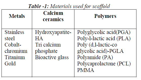
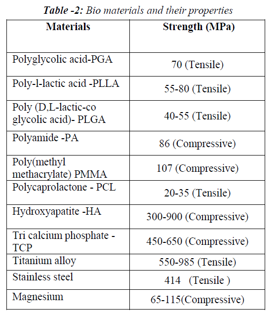
The material selection depends upon the closeness to the properties of natural bone. Hence the various properties of the natural bone are collected initially. The normal human bone has the load bearing compressive strength of about 170 MPa, Poisson’s ratio of 0.37, Young’s modulus of the bone is 20,000 N/mm2, tensile strength of the bone is 104-121 MPa and shear strength of the bone is 51.6 MPa. For any bio compactable material to act as a good scaffolding material, the properties of the scaffold implant material should be equal to that of the natural bone strength. Natural bone is a combination of polymer and ceramic composite. The material for scaffold is selected such that it should be bio-compatible and biodegradable. The material given in Table 1 has been preferred as suitable material for porous structured scaffold fabricated [1,2]. Table 2 gives the strength value of different biomaterials [3]. In this work, Polyamide 12 is selected for fabricating scaffold as it is ready available at low cost and has high strength.
3. Rapid Prototyping methods for fabricating scaffold
A large number of additive technologies are available which includes [4,5]
i. Selective Laser Sintering (SLS)
ii. Stereolithography (SLA)
iii. Fusion Deposition Modeling (FDM)
iv. Laminated Object Manufacturing (LOM)
v. 3D Printing (3DP)
i . Selective Laser Sintering
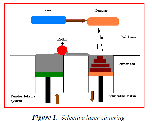
Selective laser sintering works with a high laser power source. The laser beam spread over the surface of thermoplastic powder fuses the cross-sections of the powder material, layer by layer. When one layer is completed, the fabrication process is repeated by lower down the powdered bed and adding a new layer of part material as shown in Figure 1.
ii. Stereo lithography
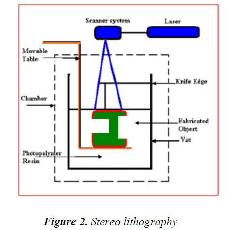
Stereo lithography is process in Rapid Prototyping is shown in Figure 2. A computer controlled UV laser power passes to the build surface of the liquid plastic material. The laser fuses the liquid material and therefore the liquid portion of the material becomes harder. After the completion of one cycle, the build portion will move downward. Therefore the UV laser beam will travel to the next cycle. Thus the fabrication process is repeated up to the completion of final build.
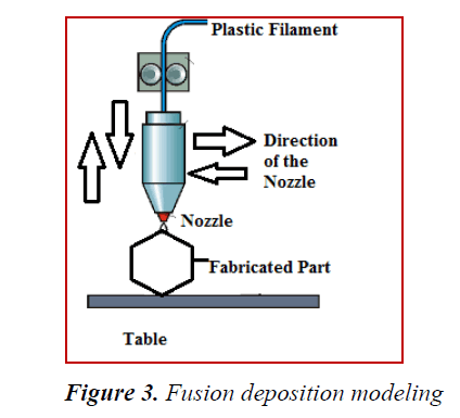
iii. Fusion Deposition Modeling
The Fused Deposition Modeling (FDM) process is a melted thread of plastic pass onto a laid down build-platform layer by layer through an extrusion nozzle as shown in Figure 3. The nozzle is contained by a mechanical device and a computer aided manufacturing programmed software produces the object model. Instead of beating the build platform surface, the liquid material solidifies in a build portion and the platform will step down, and the next layer of the liquid formed on the top surface. This process repeated until the designed model is completed.
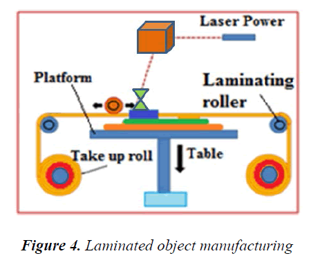
iv. Laminated object Manufacturing
Laminated Object Manufacturing (LOM) is the rapid prototyping technique of creating models with layers of adhesive coated plastic, paper or metal is then sliced with a laser of the required shape as shown in Figure 4.The internal architecture separation of the model is sliced in to a set of small cube portions and also rapidly removes the build portion. This process is less expensive and producing fine accuracy parts compare with other RP methods.
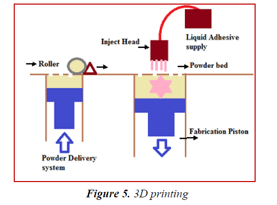
v. 3D Printing
3-D printing creates the object models by spraying the liquid material through ink-jet printer nozzles on a layer of metallic or ceramic powder, by creating a solid thin slice portions as shown in Figure 5. Thus the fabricating process is repeated for each slice, up to the model is completed as a finalized model. Then the fabricated part is fired in to a furnace to sinter the powder. After the sintering results the object is infiltrated with metal, and it receives the final build model. This process is very quick for produces the parts.
4. Design of Porous Scaffold
RP machine is a computer aided system in which CAD model of a required structure is to be interfaced in STL format. The scaffold should contain interconnected holes to satisfy required porosity level. Porosity is an essential parameter to ensure sufficient supply of nutrients and metabolites. The porosity is calculated as the percentage of void voxels relative to the total number of voxels within the scaffold model. Pore size and shape generally influences porosity and strength. Since porosity and strength are inversely proportional, the optimum pore size is to be selected to get the required strength. The design of the model also plays an important role in maintaining the strength of scaffold. SOLIDWORKS software is used to create many such porous structure models with different pore size. The scaffold design for femur bone tissue culture applications involves many parameters that directly influence the rate of bone tissue growth on to its micro structural area or surface. So, the scaffold required to be designed for mechanical load bearing capacity and mass transport.
The important parameters considered for designing scaffolds are [6]
• Porosity ranges – 40to 70% for cortical bone
• Pore size
• Pore interconnectivity
• Load bearing capacity
• Easy cell penetration
• Permeability of culture medium
• Maintenance of cell phenotypes
• Adequate mechanical properties
• Controlled biodegradation
• Ease of fabrication
The following four models with different unit cell configurations were designed for porous structured bone scaffold;
i. Cubical pore model
ii. Spherical pore model
iii. Shifted cubical pore model
iv. Shifted spherical pore model
The pore size is kept constant as 400μm for all the scaffold models. When the porosity level increases with mechanical load bearing capacity is decreases and tissue culture growth increases. So the pore size was fixed based on the required strength of the scaffold. The interconnectivity varies for different scaffold models. The porosity varies from 30 % to 70 % for scaffold models.
Porosity is defined as the ratio of void volume to the total volume of the specimen the porosities, that were selected were 40 %, 50%, 60%, 70% based on the least possible porosity range requirement for mineral dissemination. The minimum pore size was decided as 400μm for efficient dissemination. The dimension of the unit cell are modified by varying the gap between pores and the required porosity is obtained.
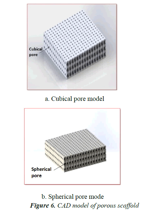
The cubical pore scaffold model has an internal pore in the architecture of a cube and interconnected by square channels of size 400μm.The unit cell size is kept constant at 1600μm and to bring the required porosity the material portion is removed from within the cell. The spherical pore scaffold model is a symmetric model with voids in the architecture of spheres and these voids connected by square channels. This model is convoluted in design. It was designed based on the improving the mechanical properties. The cubical pore model and spherical pore model as shown in Figure 6.
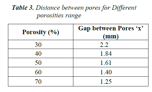
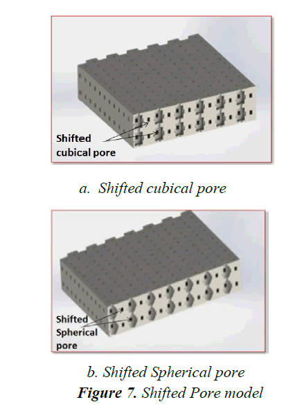
The shifted scaffold design improves the interconnectivity and the strength of the scaffold by shifting the pores by a distance so that a pore is directly not below another pore thus increasing the strength and interconnectivity .The shifted cubical pore scaffold model with top layer showing the shifted pores as shown in Figure 7. The Table 3 shows the dimensions of unit cells for different porosities.
The complex design in this method with a minimum dimension of 400 μm made the models difficult to fabricate. So the pore size was increased to 0.8mm and instead of removing the material from inside, only the pore was cut from the solid mass in three mutually perpendicular directions to obtain the required porosity [7]. The unit cell size is determined based on trial and error method and then the whole solid is designed.
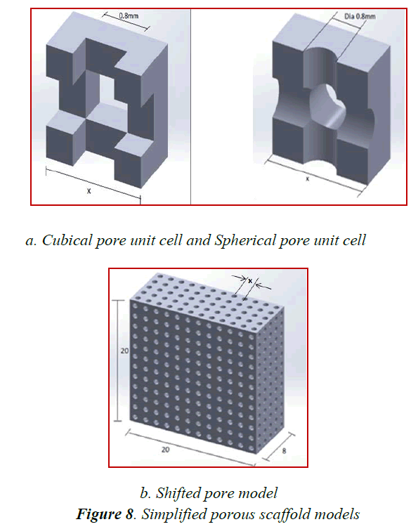
The cubical pore scaffold model was designed in shifted form. The shifted distance was half the pore size ie 400μm. From 20 x 20 x 8 mm solid block the pores were cut out according to the calculated dimensions. The spherical internal pore was replaced with cylindrical pore to make the design process similar to cubical pores (i.e.,) cutting circular channels in three mutually perpendicular directions. The diameter of the cylindrical pore was kept constant as 800μm and size of the unit cell was changed to obtain the required porosity level. From a solid block of 20 x 20 x 8 mm the pores are cut out at the calculated intervals to obtain the required specimen.
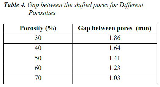
The unit cell showing the internal architecture of cubical pore and a cylindrical pore block is shown in Figure 8. The shifted cylindrical model is created in a similar way as the shifted cube specimen. The shift distance is the same as the shifted cube model i.e400μm.The shifted cylindrical scaffold model of 20x20x8 mm dimension is shown in the Figure 8. The Table 4 shows gap between shifted pores for different porosities.
Totally there are 4 types of pore shapes and 5 different porosities giving a total of 20 different models to be analysed. To simplify the analysis process first the pore types were analyzed and the best among the type is selected in a particular porosity [8,9]. All porosities are modelled on the best performing pore type and then they are analyzed and compared to give the best results. The best porosity range model is selected for manufactured and to be experimented.
5. Fabrication of porous scaffold using SLS Technique
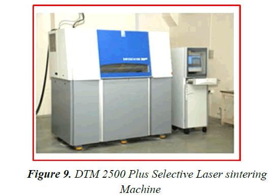
The selective laser sintering DTM 2500 Plus machine as shown in Figure 9 is selected to fabricate the scaffold. In this research work the selective laser sintering (SLS) technique is adopted in rapid prototyping [10,11]. This method is adopted because, the materials required to fabricate the scaffold are available only in powder format. Hence SLS technology was followed, [12].
SLS provides a cost effective and efficient method to produce a scaffold to match the complex anatomical geometry. Solid freeform fabrication techniques enable design and fabrication of anatomically build the scaffolds with varying different internal architectures, thereby permitting specific control over pore size, porosity level permeability range and stiffness of the product. Control over these mechanical and biological characteristics may enhance cell infiltration and mass transport of nutrients and metabolic waste throughout the scaffold.
Porous PA12 scaffolds were computationally designed and then fabricated by selective laser sintering machine. The performance of the scaffolds were assessed and compared with the designed porous architectures computationally.
The PA scaffolds are fabricated by varying the orientation of the building direction such as horizontal, vertical and inclined, through SLS machine with pores size of 0.8 mm. Addition of HA will improve the strength and tissue growth of the scaffold in addition of PA 12 (USP Class vi certified) and hence the scaffolds will be fabricated with various percentage of HA for the better mechanical and biological properties of the scaffold.
6. Conclusion
This research focuses on the study of available bio materials which are suitable for scaffold applications. Various rapid prototyping methods used for fabricating the scaffold structure are also discussed. The selection of material depends on the strength, cost and its degarding behavior. The rapid prototyping process is selected based on the physical form of the material, surface finish required and the strength requirement. The different configuration of the unit cell used in porous scaffold can be analyzed using FEA software by applying compressive load and the factor of safety and stress concentration for each model can be compared The porous scaffold models are fabricated in PA material in different model building orientation. The fabricated porous scaffold specimens will be tested for mechanical and biological characteristics with / without the incorporation of HA composition in future.
Acknowledgements
The authors are thankful to the Department of Science and Technology (DST), Government of India, for their Support and funding for the above research.
References
- N.K.Vail, L.D.Swain, W.C.Fox “Materials for biomedical applications” Materials & design 1999; 123-132.
- Gérrard Eddy et al “Biomedical Magnesium Alloys: A Review of Material Properties, Surface Modifications and Potential as a Biodegradable Orthopaedic Implant” American Journal of Biomedical Engineering 2012; 2(6): 218-240
- Doo Yeon Kwon et al ” Biodegradable stent” Journal of Biomedical Science and Engineering 2012; 5 (4):
- Matthew C. Frank, PhD, Ashish Joshi “Patient specific bone implants using subtractive rapid prototyping” Proceedings of the Solid Freeform Fabrication Symposium, Austin, TX, 2010.
- P.Berce, H.Chezan, N.Balc “The application of rapid prototyping technologies for manufacturing the custom implants” Rapid prototyping and rapid tooling, ESAFORM Conference 2005
- Brahatheeswaran, Dhandayuthapani, Yasuhiko Yoshida, Toru Maekawa, D. Sakthi Kumar “Polymeric Scaffolds in Tissue Engineering Application: A Review” International Journal of Polymer Science Volume 2011; 1-19
- Abdul Manaf abdullah, Tuan Noraihan Azila,“Fabrication and evaluation of polyamide composite as a potential biomaterial for tissue engineering applications: A preliminary review” Regenerative research 2014; 3 (2): 62-64
- Somkid A ,Kaorapapong k, Wiwatanapataphee B “Three Dimensional simulation of Femur bone and implant in femoral canal using finite element method”, International journal of mathematics and computers in simulation 2010; 4(4):
- BenteMoreseth, NinaEmaus, Lonejorgensen “Physical activity and bone: The importance of the various mechanical stimuli for bone mineral density. A review” Norsk Epidemiologi 2011; 20(2):173-178.
- Detlef kochan, Chua chee kai, Du Zhaohui “Rapid prototyping in the 21st century” Computers in industry 1999; 39(1): 3-10.
- R.Petzold, H-F Zeilhofer “Rapid prototyping technology in medicine-basics and applications” Computerized medical imaging and graphics 1999; 277-284.
- E.Sachlos and J.T.Czernuszka “ Making tissue Engineering scaffolds work - Review on the Application of scaffold freeform fabrication technology to the production of tissue engineering scaffolds” European cells and materials 2003; 5(1): 29-40.
