ISSN: 0970-938X (Print) | 0976-1683 (Electronic)
Biomedical Research
An International Journal of Medical Sciences
Research Article - Biomedical Research (2017) Artificial Intelligent Techniques for Bio Medical Signal Processing: Edition-I
Brain computer interface for vehicle navigation
1Department of Electronics and Communication Engineering, SSM Institute of Engineering and Technology, Dindigul, Tamil Nadu, India
2Department of Biomedical Engineering, SSN College of Engineering, Chennai 603110, Tamil Nadu, India
3Department of Electronics and Communication Engineering, PSNA College of Engineering & Technology, Dindigul, Tamil Nadu, India
- *Corresponding Author:
- G Mohan Babu
Department of Electronics and Communication Engineering
SSM Institute of Engineering and Technology
Tamil Nadu, India
Accepted on February 15, 2017
Brain computer interface can be defined communication pathway between a person and their external environment with the aid of Brain signals. The proposed interface aims to make use of the intended movement as a command signal that mimics the actual movement to control vehicle routing application. This can be in health care for Neuro-rehabilitation. The electrical activity of the brain in the frontal and central lobes is acquired using Electroencephalograph (EEG) using wearable active electrodes. The acquired EEG signals are conditioned and processed to extract the Mu waves and eye blink they were used as control signals for vehicle navigation. By using this module the vehicle can be navigated and controlled automatically in real time without user’s assistance. It can also be used for physically challenged people to control the vehicle who lost their limbs due to accidents. This module can be further developed as an auto mode which programs the vehicle to override the function of humans whenever they feel drowsy or lethargic.
Keywords
EEG, Eye blink, MU Waves, Vehicle Navigation.
Introduction
EEG is the process of acquiring the electrical activity of the brain with the help of electrodes placed on the scalp. BCI basically uses EEG signals obtained during the process of imagination and they find wide applications like rehabilitation, neural engineering, and gaming and subject training [1,2]. Brain computer interface uses the electrical activities of the brain to control various applications. most of the applications were focused on cursor movement control in personal computers to communicate to the external world. In Brain Computer Interface systems decisions are made based on very short segments of EEG data which can be used for controlling hardware applications such as wheelchairs and robots. Driven by the wide application of BCI they are also used for gaming application as it provides a safe and motivating environment for patients during training or Rehabilitation [3,4]. The novelty and challenges apart from them being a suitable platform to bring this new interaction modality to the general population. Birbaumer [5] developed thought translation device for the paralytic patients to communicate to the external world. Galán [6] developed brain controlled wheelchair which makes the physical challenged people to navigate around. BCI also founds application in modality of control, for evaluation of the user defined adaptive application, or to build user interfaces. The EEG signals obtained during the process of imagination were also find wide applications in Neuro rehabilitation, gaming and Neuro feedback training [3,7] The BCI application aims for a closed loop control by placing the electrodes on the sensorimotor cortex and effectively extracting the brain activity for various controls. The non-invasive placement of electrodes are limited as they were frequently prone to external noise like power line inference and physiological noise like muscle activity This degrades the acquired signals so an effective EEG pre-processing should be implemented. The present work aims to develop BCI using the actual and imaginary hand movement for vehicular control.
The EEG signal obtained during voluntary eye blink condition [4], produces clear signals with larger amplitude (approximately 260 mV) compared to that of the normal EEG (10-100 mV). Also, the frequency of the EEG wave containing the eye blink will be around 4-7 Hz, which is different from that of the normal EEG wave in an active state which is approximately 8-30 Hz. [8]. Mu rhythm in the alpha-range activity (8-14 Hz) is seen over the sensorimotor cortex and the event related desynchronization that led to the suppression of Mu power during task (i.e., movement of hand in actual and imaginary) Contralateral activity which is associated with the suppression of Mu power in C3-CZ signal during the movement of right hand and suppression of Mu power in C4- CZ signal during the movement of left [9,10]. The Mu rhythm is in the alpha-range activity that is seen over the sensorimotor cortex of 8-14 Hz frequency which is a region of the cerebral cortex involved in the planning, control, and execution of voluntary movements. Mu wave characteristically attenuates with movement of the contralateral arm (or mental imagery of movement of the contralateral arm) [11]. Normally these waves synchronise when there is a refusal/not planned movement, but they suppress when there is affirmative/planned movement [12,13]. Babiloni [14] stated the EEG recording from CZ, C3 and C4 provide the roundabout measures of cortical activity left and right sensorimotor cortices. And Electroencephalography (EEG) provides the cost effective noninvasive technique to measure the Mu waves across the sensorimotor cortex through surface electrodes [15]. The key objective of this project is to design a BCI based vehicle navigator to navigate the vehicle. This module is used to navigate the vehicle with the help of human brain activity by acquiring the EEG signals by placing the wearable active electrodes on the scalp over the motor cortex.
Methodologies
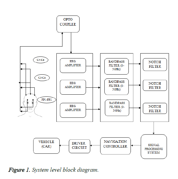
Accordingly, a standalone system for navigation system was proposed the module comprises of an EEG amplifier unit which is used to condition the input signals acquired from the frontal (FP1-FP2) and the central electrode positions (C3-Cz and C4-Cz) and to remove the noise from these signals (Figure 1). The acquired EEG signals are in the order of micro volts; hence these signals are amplified using INA122 which is precision instrumentation amplifier. The Opto coupler circuit is connected to the EEG amplifier which acts as isolation amplifier thereby isolates the high voltage threats to users. The amplified signal is then fed to the band pass filter whose frequency range is about 50 Hz. The filtered signal is fed to Data Acquisition system (NI-DAQ) as analog input signal for signal processing.
The EEG features such as eye blink and MU wave (8-13 Hz) were extracted and these features are converted into pulses which are fed to the navigation controller. The pulse corresponding to the eye blink is used to start the vehicle and the pulse corresponding to the MU wave is used to move the vehicle right or left based on the MU power estimation. Initially, when the subject blinks his/her eye, the DC motors in the vehicle are triggered and it moves forward. Later, when the subject thinks to navigate the vehicle to the right or left, MU wave is generated in the central lobes (C3-Cz and C4-Cz). Based on the comparison of the power of the MU wave from both positions of the central lobes, the vehicle will turn to the left or right. And, when the subject blinks his/her eye consecutively for more than one time, the module will be turned off. The signals were acquired from Frontal (FP1-FP2) and central (C3-Cz-C4) positions.
Experimental protocol for EEG acquisition
In this proposed work, voluntary eye blink is used to start and control the vehicle in the forward direction. Hence the voluntary eye blink can be acquired by placing the electrode on the frontal lobe (FP1-FP2) as shown in Figure 1. The MU wave is used for the navigation of the vehicle to the right and left sides. Hence the MU wave is acquired with the help of visual stimuli and right and left hand movements by following the experimental protocol as shown in Table 1.
Visual stimuli
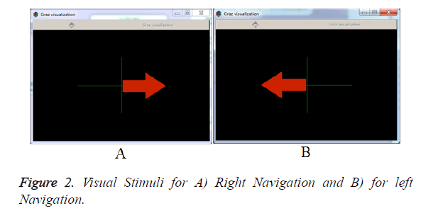
In order to assist the subject during imagination of hand movement, visual cues are given. They improve the focus of the subject and standard software called OpenVIBE is used to provide visual cue. The visual stimuli (Figure 2) for left and right navigation are also shown to the subjects. As a result of this experiment, it was found that the EEG signal acquired during real and imaginary hand movements are well correlated [16,17]. Mu rhythm is also observed in the sensorimotor region during the motor movement or intended motor movements. Hence the MU wave is extracted from the EEG signals and it is used as a control signal for the navigation of the vehicle.
Implementation
Hardware Implementation
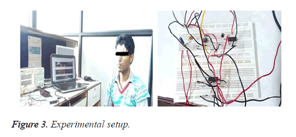
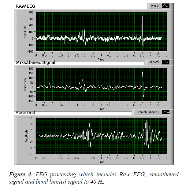
Figure 3 shows the experimental setup. EEG signals are in the order of micro volts hence they are amplified in two stages. The first stage of amplification is done by INA122 which is a high gain, precision instrumentation amplifier whereas the second stage of amplification is done by LF356. The amplified signal is fed to a band pass filter designed using LM324 to filter the acquired EEG signals whose frequency range is 0-50 Hz. The noise due to the power line interference is removed by using a notch filter (50Hz) shown in Figure 3. The filtered EEG signals are fed to LabVIEW via NI-DAQ for feature extraction. The preprocessing of the acquired raw EEG at C3, Cz and C4 were mandated as the contra lateral activity recorded would be of low voltage and this was attenuated by the skull along with power line inference .so an efficient processing technique was implemented to extract the Mu wave power. The raw EEG signal was smoothened and low pass filter of 40 Hz was implemented after this the Mu waves was obtained by using band pass filters with the cut-off of 8 to 14 Hz.
EEG preprocessing: A moving average filter with rectangular window of order 15 was implemented as they are primarily used for noise reduction in the EEG signal. A subset of data is taken whose average is computed and the first value of the subset is replaced by the average value. For computing the average of the next subset, the first value is excluded and the subset moves like a sliding window shown in Figure 4.
Software implementation
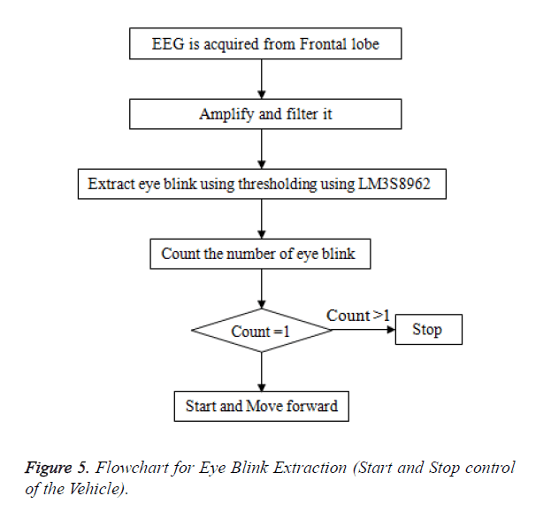
After the acquisition of the EEG signal from the frontal lobe, the signal is amplified and fed to NI-DAQ module for extracting the eye blink using thresholding, and then the pulses are counted. If the count is equal to one, the vehicle starts and moves forward. Else if the count is greater than one, the vehicle is turned off. Figure 5 shows the flowchart for extracting the eye blink signal.
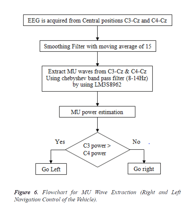
Figures 5 and 6 shows the flowchart for MU wave extraction. The EEG signal acquired from central positions C3-Cz and C4- Cz are amplified and fed to NI-DAQ for extracting MU waves using Chebyshev band pass filter (8-14 Hz) [10]. Chebyshev Bandpass filters: The frequency spectrum of the EEG signal lies between 0.1 Hz to 40 Hz. So the next step would be to band limit the signal to the desired frequency range. The Chebyshev filter was chosen due to its sharper roll off and stability characteristics [18,19]. In order to extract the actual and imaginary movement sharper cut-off becomes mandatory as these extracted signals were used as control signals so based on previous researchers' findings Chebyshev band pass filters was selected for extracting the Mu waves feature extracted was depicted in Figure 7. After extraction, the power of the MU wave from both the positions are estimated and compared. If the power of the signal from C3-Cz is greater than C4-Cz the vehicle navigates towards the left and if the power of the signal from C4-Cz is greater than C3-Cz the vehicle navigates towards right.
Feature extraction and controlling
The contra lateral activity of movement defined as the left hemisphere of the brain controls the right side of the body and the right hemisphere controls the left side of the body. So the movement of the right hand is associated with activity in the left hemisphere of the brain. The Mu wave suppression at the left part of the brain during right hand movement/imagining moving are reflected at C3 and C4 reflects the left hand association [14,20]. So based on this for this work C3 and C4 electrode location were selected for acquiring EEG signals.
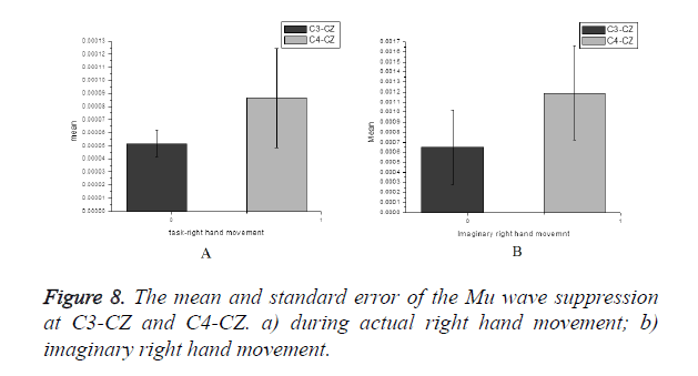
The actual hand moves and imaginary hand movement in left and right hands were evaluated by calculating the mu power and correlating them. The Figure 8a shows the mean and standard error of the Mu wave suppression at C3-CZ and C4- CZ during actual right hand movement and Figure 8b during imaginary right hand movement at same locations.
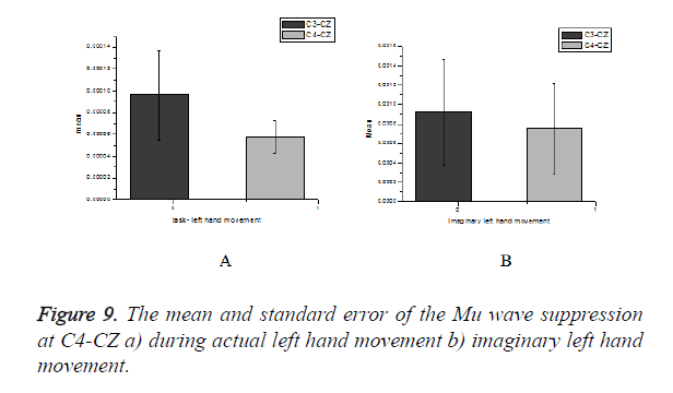
The Figure 9a shows the mean and standard error of the Mu wave suppression at C3-CZ and C4-CZ during actual left hand movement and Figure 9b during imaginary left hand movement at same locations.
The extracted signals are converted into a pulse. Initially, a pulse with respect to the eye blink is counted by the counter. If one blink is detected, the pulse is fed as an analog input to MSP430 launch pad that instructs the vehicle to start and move forward. The power of the MU wave from C3-Cz and C4-Cz positions is calculated and both the powers are compared by the comparator. If the subject focuses on the visual stimuli for left navigation shown in Figure 2B, the power of the MU wave from C3-Cz becomes high and the pulse corresponding to this signal is taken as pulse width modulation (PWM) output from NI-DAQ. It is fed to MSP430 that instructs the vehicle to navigate towards left. Similarly, if the subject focuses on the visual stimuli for right navigation shown in Figure 2A, the power of the MU wave from C4-Cz becomes high and the pulse corresponding to this signal is taken as PWM output from NI-DAQ. It is fed to MSP430 that instructs the vehicle to navigate towards right. If the subject is at rest or if the voluntary eye blink is detected consecutively for more than one count, the vehicle will be turned off.
Results
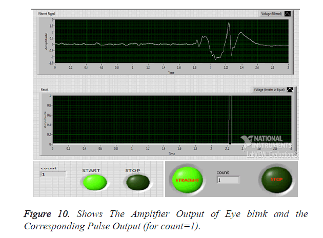
The Raw EEG signal acquired from the amplifier is processed using the software NI LabVIEW. The primary purpose of signal processing is to remove noises present in the signal and extract the feature of interest such as eye blink and Mu waves. The amplifier output of the eye blink which is converted into pulse using LabVIEW. This pulse is used to start the vehicle and to go straight as indicated by an LED shown in Figure 10.
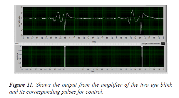
The output for two eye blink and corresponding pulses for more than one count which is indicated to stop the vehicle was shown in Figure 11.
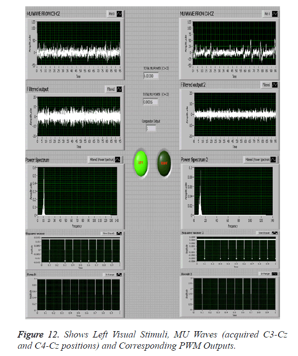
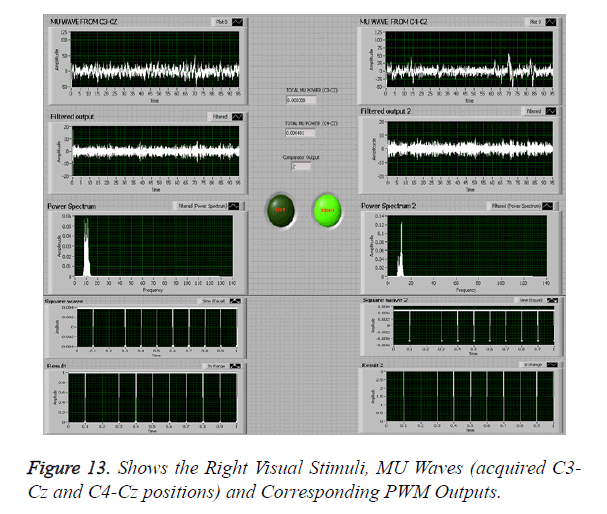
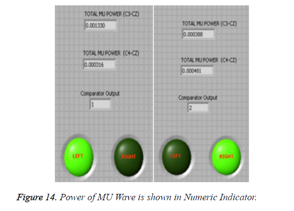
The MU waves that are converted into PWM which is used as control signal for left and right navigation is also shown in Figures 12 and 13 MU waves acquired from central positions when the participants were asked to focus on the left and right visual stimuli. The power of the MU wave estimation indicated in the numeric indicator with respect to left (C3>C4) and right navigation (C4>C3) shown in Figure 14. For vehicle navigation, two distinct signals are used- left and right. These control signals are extracted. Control signals are computed based on the mean power values of the processed signal [1,8,21].
The power values for the signal in the desired frequency range [1,10] are calculated. The power of the signal in the Mu frequency band is computed for the bipolar montages- C3-CZ and C4-CZ corresponding to left and right visual cues respectively. During the movement of the right visual cue, there is suppression of Mu power in the C3-CZ montage and the condition C3<C4 is executed and the output value is set to 2 (indicated as ‘RIGHT’ in LED) by the comparison logic.
Similarly during the movement of left hand C3>C4 and the output is set to 1 (indicated as ‘LEFT’ in LED).
Implementation in MSP430
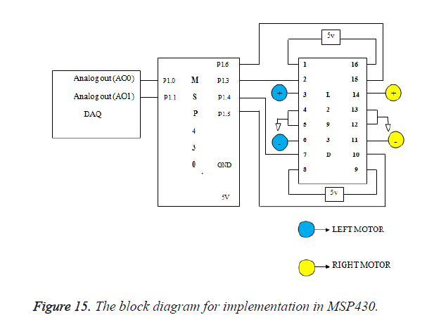
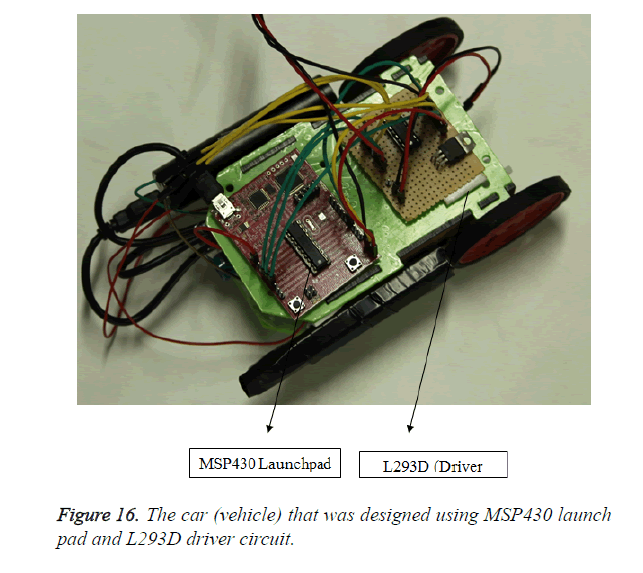
The Figures 15 shows the connections for implementation in MSP430 launch pad. The extracted features such as eye blink and PWM of MU waves are taken as analog output signal through output pins in DAQ and L293D driver wass used to impel the left and right motors. These signals are fed into as analog input signals through analog input ports P1.0 and P1.1. The ports P1.3, P1.4 and P1.5, P1.6 are connected to left and right motors in the vehicle. The modeled car navigates according to the signal received from DAQ shown in Figure 16. It is programmed using software called ENERGIA.
Conclusion
A Brain Computer Interface that is developed to control the vehicle navigation could be controlled without the user’s assistance. This application can be used by all users and can be extended for paralytic patients and this module can be further developed as an auto mode navigation system in which the vehicle can be programmed to override the function of humans whenever they feel drowsy or lethargic. In the current study have some limitations, the sample size was less and in order to enumerate the outcome sample size should be increased and this device was tested for normal healthy adults. In order to implement this for commercial purpose the number of trials should be increased. Instead of placing the electrodes on the scalp if they are placed in the cortex itself, it would provide a better result and this can be extended to individuals who have difficulty in controlling the hand movement.
References
- Liao LD, Chen CY, Wang IJ, Chen SF, Li SY, Chen BW, Lin CT. Gaming control using a wearable and wireless EEG-based brain-computer interface device with novel dry foam-based sensors. J Neuroeng Rehab 2012; 9: 5.
- Bram van de L, Reuderink B, Plass-Oude Bos D, Heylen D. Evaluating user experience of actual and imagined movement in BCI gaming. Int J Gaming Comput Mediated Simulations 2010; 2: 33-47.
- Pfurtscheller G, Neuper C, Müller GR, Obermaier B, Krausz G, Schlögl A, Scherer R, Graimann B, Keinrath C, Skliris D, Wörtz M, Supp G, Schrank C. Graz-BCI: State of the Art and Clinical Applications. IEEE Transact Neural Syst Rehab Eng 2003; 11: 177-180.
- Fok S, Schwartz R, Wronkiewicz M, Holmes C, Zhang J, Somers T, Leuthardt E. An EEG-based brain computer interface for rehabilitation and restoration of hand control following stroke using ipsilateral cortical physiology. In 2011 Annual International Conference of the IEEE Engineering in Medicine and Biology Society, IEEE, 2011.
- Birbaumer N, Kubler A, Ghanayim N, Hinterberger T, Perelmouter J, Kaiser J, Flor H. The thought translation device (TTD) for completely paralyzed patients. IEEE Transact Rehab Eng 2000; 8: 190-193.
- Galán F, Nuttin M, Lew E, Ferrez PW, Vanacker G, Philips J, Millán JDR. A brain-actuated wheelchair: asynchronous and non-invasive brain–computer interfaces for continuous control of robots. Clin Neurophysiol 2008; 119: 2159-2169.
- Teplan M. Fundamentals of EEG measurement. Measurement Sci Rev 2002; 2: 1-11.
- Blankertz B, Müller KR, Curio G, Vaughan TM, Schalk G, Wolpaw JR, Schlögl A, Neuper C, Pfurtscheller G, Hinterberger T, Schröder M, Birbaumer N. The BCI Competition 2003: Progress and Perspectives in Detection and Discrimination of EEG Single Trials. IEEE Transact Biomed Eng 2004.
- Kumar D, Poole E. Classification of EOG for human computer interface. 24th Annual Conference and the Annual Fall Meeting of the Biomedical Engineering Society EMBS/BMES Conference, 2002.
- Balasubramaniam G, Pooja R, Eswari R, Bhavani J. Brain Computer Interface for Gaming Applications. Neuroepidemiology 2014; 43: 104 -105.
- Pineda JA. The functional significance of mu rhythms: translating “seeing” and “hearing” into “doing”. Brain Res Rev 2005; 50: 57-68.
- Virji-Babul N, Moiseeva A, Cheunga T, Weeks D, Cheynec D, Ribary U. Changes in mu rhythm during action observation and execution in adults with Down syndrome: Implications for action representation. Neurosci Lett 2008; 436: 177-180.
- Muthukumaraswamy SD, Johnson BW, McNair NA. Mu rhythm modulation during observation of an object-directed grasp. Cognitive Brain Res 2004; 19: 195-201.
- Babiloni C, Carducci F, Cincotti F, Rossini PM, Neuper C, Pfurtscheller G, Babiloni F. Human movement-related potentials vs desynchronization of EEG alpha rhythm: a high-resolution EEG study. Neuroimage 1999; 10: 658-665.
- Altschuler EL, Vankov A, Wang V, Ramachandran VS, Pineda JA. Person see, person do: Human cortical electrophysiological correlates of monkey see monkey do cells?. J Cognitive Neurosci 1998; 10: 91-91.
- Wang Y, Gao X, Hong B, Gao S. Practical designs of brain–computer interfaces based on the modulation of EEG rhythms. In Brain-Computer Interfaces. Springer Berlin Heidelberg, 2009.
- Athanasiou A, Lithari C, Kalogianni K, Klados MA, Bamidis PD. Source Detection and Functional Connectivity of the Sensorimotor Cortex during Actual and Imaginary Limb Movement: A Preliminary Study on the Implementation of eConnectome in Motor Imagery Protocols. Adv Human Comput Interact 2012.
- Ke L, Li R. Classification of EEG signals by multi-scale filtering and PCA. Proceedings of the IEEE International Conference on Intelligent Computing and Intelligent Systems ICIS ‘09. IEEE, 2009.
- Subramanian M, Geethanjali B, Seshadri NG, Venkat B, Vijayalakshmi R. Visualization of Brain Activation during Attention-Demanding Tasks Using Cognitive Signal Processing. Int J Cognitive Informat Nat Intell (IJCINI) 2017; 11: 60-81.
- Crawcour S, Bowers A, Harkrider A, Saltuklaroglu T. Mu wave suppression during the perception of meaningless syllables: EEG evidence of motor recruitment. Neuropsychologia 2009; 47: 2558-2563.
- Ding Q, Tong K, Li G. Development of an EOG (electro-oculography) based human-computer interface. In 2005 IEEE Engineering in Medicine and Biology 27th Annual Conference, 2006.
